- qIXmo5v.jpg (659.18 KiB) Viewed 1767 times
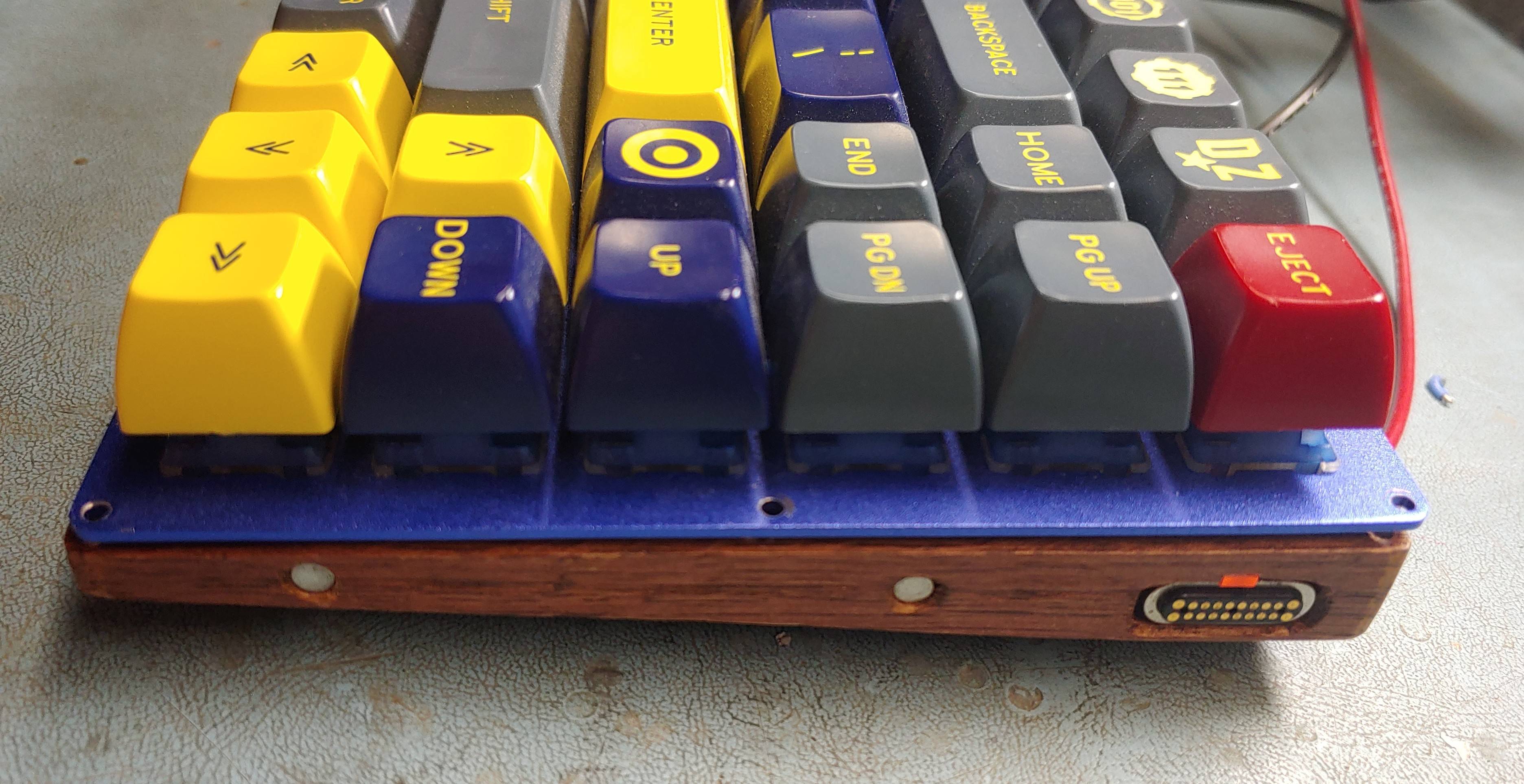
Progress has been made! I am as close as I ever have been to finishing fully!
I do still have wiring to do, but the hardest part is done.
I have successfully disassembled the USB-C magnetic connectors,
and successfully installed them into the keyboard and number pad trim pieces!
- 3dO5fbT.jpg (346.25 KiB) Viewed 1767 times
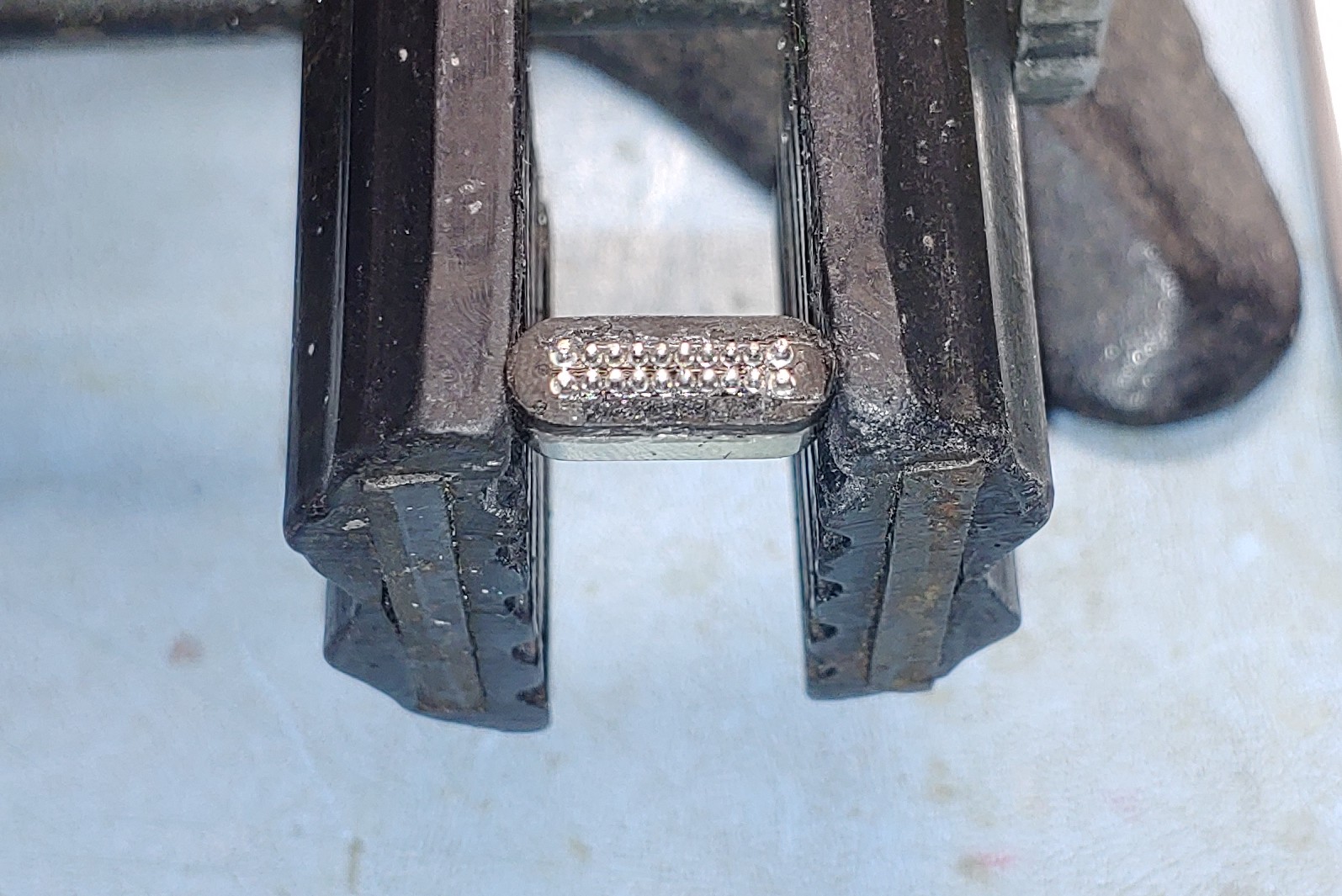
This part went better than I expected, though it was still rather difficult. I was very concerned about damaging the connectors, but they seemed to take the heat of my hot air rework station well. I suspect there was some sort of thermo-plastic used in their construction. It took a lot more heat and effort to desolder the half of the connector with the pogo pins from the half with the circuit board and female USB-C socket.
- mT69dol.jpg (323.33 KiB) Viewed 1767 times
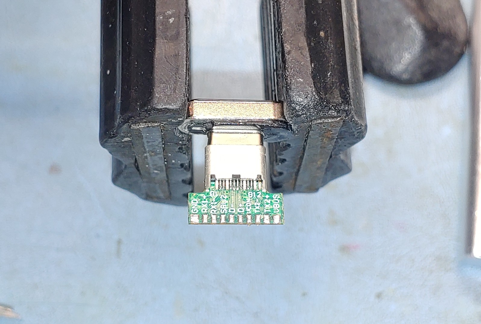
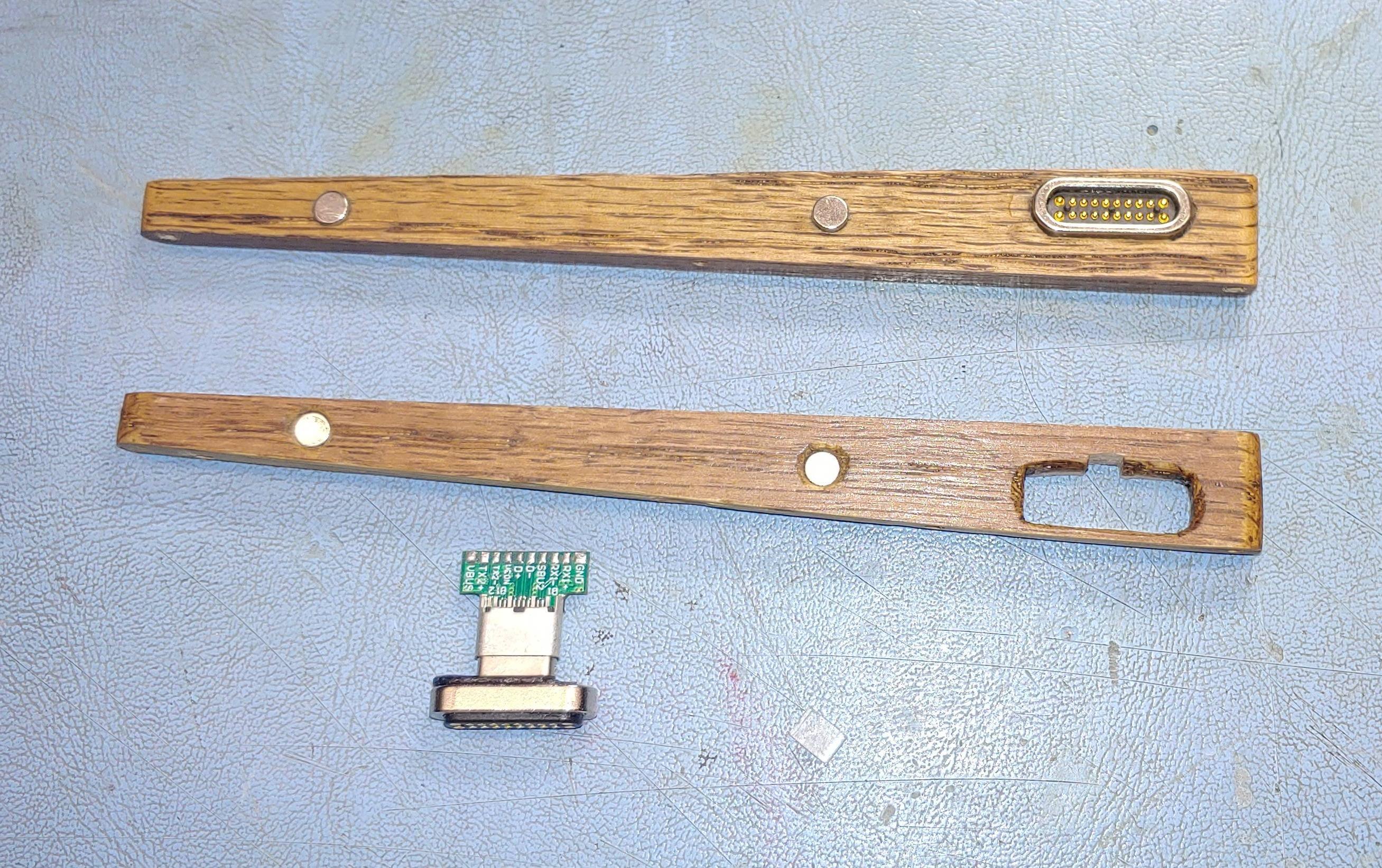
Turns out the USB-C socket was just so new, that it took a lot of force to fully insert the male USB-C plug into it, and get a solidly registered locking insertion. Once the two were together, they were very solidly joined. As it just so happens, both the socket and plug readily accepted solder, so I simply soldered the two halves together into an absolutely permanent joint. The male plug side, as mentioned in the previous post, features the contact cups that the pogo pins mate to when the magnetic connectors are joined. With the Pogo connector separated from the PC board, I had large enough solder pads / solder posts that I can individually solder wires to. Electrically, when looking from either the top or the bottom of the PC board, in the orientation shown in the picture, Ground is always the leftmost pad, and positive always the rightmost pad This does mean that 2 pads are always wired as ground, and 2 pads always wired as positive, leaving 16 remaining pads to carry signals. This is actually exactly perfect, as we have 12 columns, 3 rows, and one LED PWM signal... a total of 16. The board had an integrated LED and resistor wired between ground and positive. I removed it, cause even though i like green, It wasn't what I wanted for this keyboard.
- wRo2ZrS.jpg (921.3 KiB) Viewed 1767 times
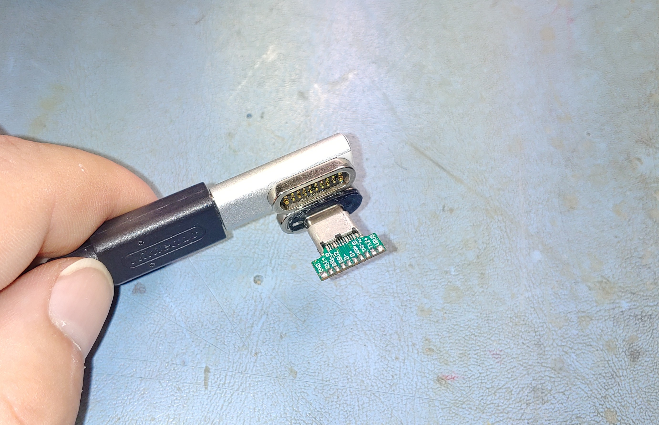
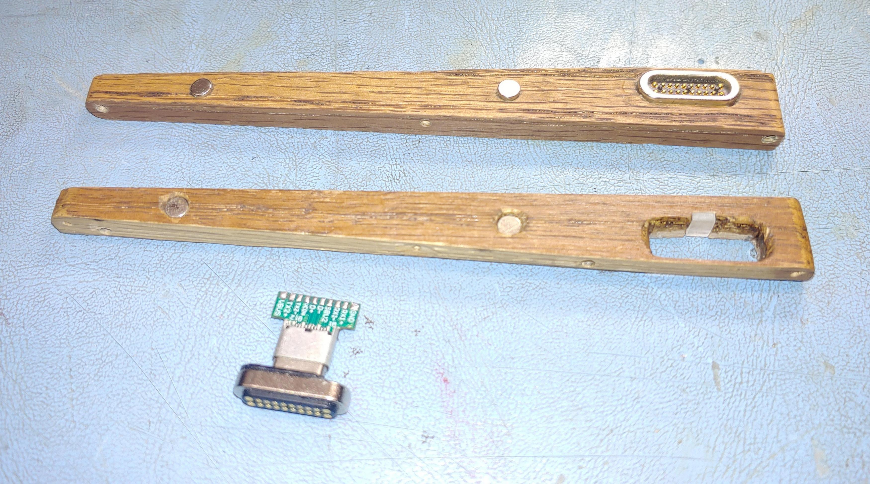
On a side note, I had to epoxy the ring magnet back onto the contact cup connector, due to my failed attempt to trim the plastic. When I reattached it, I made the error of putting it on backwards, but this has the positive effect of making it so that none of my actual USB-C magnetic connectors or cables are attracted to the connector. They repel, and try to push them above or below. I decided to flip the magnet on the Pogo pin connector too, essentially reverse keying these, as a safety precaution, so no actual USB cable ever unintentionally attaches to the number pad port. The magnets were epoxied permanently in their reverse positions when i epoxied the connectors in place on the trim.
- Bs0Ovzd (1).jpg (801.79 KiB) Viewed 1767 times
The old 5-pin MagSafe connector happened to have a key on the contact cup side of the connector, and it needed to be dealt with. My solution was actually quite simple. I filed it out just a bit, got a light pipe out of my LED kit, filed it down to the correct size and shape, and epoxied it in with the connector.
- sOwceuJ.jpg (890.43 KiB) Viewed 1767 times
It nicely fills the gap the old keyway leaves, and will provide me with a port accentuating power LED.
- 7fDceSE.jpg (828.5 KiB) Viewed 1767 times
I used the same type of amber LED as I used throughout all the sub-key lighting across the entire keyboard, but i chose a larger resistor value, so that it would not glow very brightly. I did decide to hardwire it into power, so it will always remain lit, so long as the keyboard itself has power... Just very dimly. I painted the backside of the LED first yellow, to reflect as much light forward as possible, then painted over that with a few layers of black, so there is no bleed through in the adjacent key switch, incase all other LEDs are switched off.
- 4PjKo61 (1).jpg (191.18 KiB) Viewed 1767 times
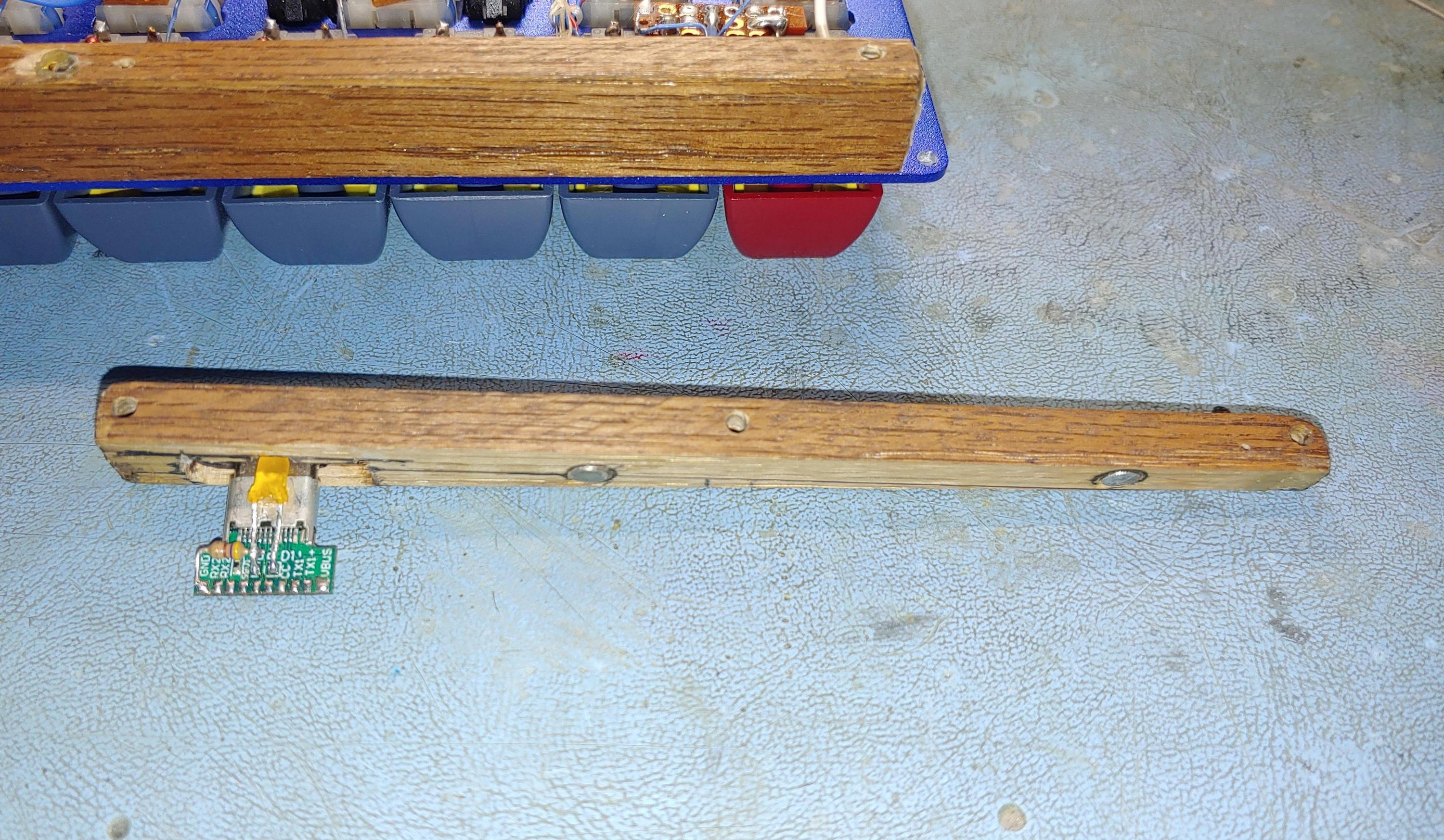
The board does stick out over the key switch, but it does clear... barely... It's close enough that I will definitely wrap the board in Kaptan tape, just to make sure it stays insulated. I've removed all the I2C circuitry and the DAC based LED controller. I reconnected the LED drivers (not visible in this pic) to a PWM output on the Teensy, and strung a second wire off the PWM output to the location of the new connector. I've also taken the sense wire, I2C Data, and I2C Clock wires and now have them terminated next to the small circuit board (they are unconnected at the moment).
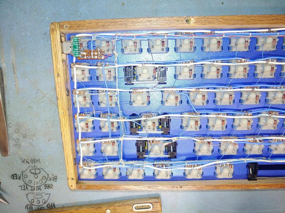
What remains to be done is wiring columns 1-12 to the connector, and actually soldering everything to the connector. With the old I2C Data and Clock wires, the Sense wire, and the LED PWM wire already strung, it means I already have LED control and the three row wires placed. On the numberpad side, I need to construct a pair of LED drivers (simple... it's two transistors and two resistors), and then just wire up the 18 connections from the connector for power, LED control, and to the already existing switch matrix wiring. There are only a few wires to connect from the LED drivers to the LEDs (2 drive wires, and a single positive wire).
I've also decided that I will run down to the hardware store and buy all new brass screws, as all the opening and closing has marred up the existing ones pretty badly. I'm gonna drop a little sawdust and wood glue into a few of the screw holes, to reform the holes, as a few are stripped out. Other errata include creating a suitable light pipe and shroud for the caps lock key, cutting the bottom plate for the number pad, and maybe finding some better rubber feet. Aside from running some wires and soldering the last bits... This is very nearly done!

Thanks to eliminating the need for a second controller, and no longer needing to figure out how to gracefully hot-plug said controller, the firmware becomes a very simple matter of simply doing a basic single controller firmware. There are well explained guides that go through this process, and I have no doubt I can put the firmware together in no time. So long as I don't get hit by work, or procrastinate, I think there's a real chance I have this working this month yet! I'm genuinely excited, most of all because software isn't holding me back anymore!
