Page 10 of 11
Posted: 07 May 2016, 01:18
by lot_lizard
So I got her soldered up, and can confirm... IT'S ALIVE via an adhoc flipper test on a couple of keys. Does anyone care to share their layout file with me? It is fun to go through the process a few times, but at this point, would just prefer the canned .l file extension if you export yours.
Also, I am at 120 on the voltage threshold, and seems to be close enough to fire. If whoever posts the layout file could tell everyone what theirs is at, we would set before auto-calibrating
I ended up using just 40 pin jumper pin wire, like the image below, and stripped off 10 cables. Then I broke it up into two sets of cables (11 / 19, splitting on the center ground pair). The jumper pin ribbon saved me from having to precut the IDE cable into individual strands since they pull apart easily. I am proud of the solder job itself, but should have taken a little more time like i$ on sizing each strand if desiring perfection
EDIT: i$... maybe add the layout file (.l extension) to the zip file?
Posted: 07 May 2016, 08:30
by idollar
lot_lizard wrote: So I got her soldered up, and can confirm... IT'S ALIVE via an adhoc flipper test on a couple of keys. Does anyone care to share their layout file with me? It is fun to go through the process a few times, but at this point, would just prefer the canned .l file extension if you export yours.
......
EDIT: i$... maybe add the layout file (.l extension) to the zip file?
Attached the file that I have used with the connector in the middle (swapped pairs)
Posted: 07 May 2016, 11:05
by lot_lizard
idollar wrote: Attached the file that I have used with the connector in the middle (swapped pairs)
Thank you... For some reason "swapped pairs" wasn't noticed when I first downloaded and tried. I thought... "I know the German layout isn't that different... is i$ a dvorak or colemak guy?!?"

Then it clicked, and I went back and read your post. I attached mine (unswapped pairs) variety below. I removed the 10-key mapping for the moment, and currently have no Fn1-3 keys or function layers. Also, 116 was the magic voltage threshold for me.
It really is exciting to see this work so nicely. I know you are probably tired of hearing people gush, but you really did an outstanding job on this stuff i$. My wife probably hates you, but I am very pleased
Posted: 08 May 2016, 15:28
by idollar
lot_lizard wrote: I know you are probably tired of hearing people gush, but you really did an outstanding job on this stuff i$.
No-one can get tired of these comments, ever.
Thanks
I will add your configuration file to the first post.
Thanks a lot
Posted: 08 May 2016, 18:45
by Hypersphere
Received my PCB. Thanks!
Posted: 08 May 2016, 18:58
by Alkhar
Hello, received my PCB. Thanks idollar
Posted: 08 May 2016, 21:42
by idollar
Hypersphere wrote: Received my PCB. Thanks!
Great !
Posted: 08 May 2016, 21:43
by idollar
Alkhar wrote: Hello, received my PCB. Thanks idollar
Great !
Posted: 10 May 2016, 17:52
by Lurch
Got my PCB today. Thanks again idollar!!!
Posted: 10 May 2016, 19:36
by hypkx
btw in my package was not a note for somebody (or me).
Posted: 11 May 2016, 07:54
by idollar
Lurch wrote: Got my PCB today. Thanks again idollar!!!
Great !
Posted: 11 May 2016, 07:55
by idollar
hypkx wrote: btw in my package was not a note for somebody (or me).
In the middle of the packing process and after the mess that I created with the notes, I decided to stop it.
Great that you have gotten the PCB !
Posted: 13 May 2016, 07:23
by idollar
Guys, there are not more spare PCBs for this GB. The last one was booked for Sayso some days ago.
I am not sending the extra ones until all the people on the regular shipping gets theirs, just in case.
HAL, Halvar, orihalcon, snoopy ... please tell us if you have received yours.
Techno Trousers ... your second unit (#27) is in your way since a week. Please keep us posted.
If anyone is interested in a new round, let me know
Posted: 13 May 2016, 08:35
by Halvar
My neigbour (male young single) has my parcel and I haven't been able to hunt him down for more than a week now. I left a note in his mailbox three days ago and it's still in there. I'm sure he only wanted to be nice but I do hate him a little bit at the moment.

Posted: 13 May 2016, 09:09
by Halvar
I like my handsome young neighbor for giving me my parcel.
This is great!
I was surprised how thin these PCBs are, no worries about bending them any more.
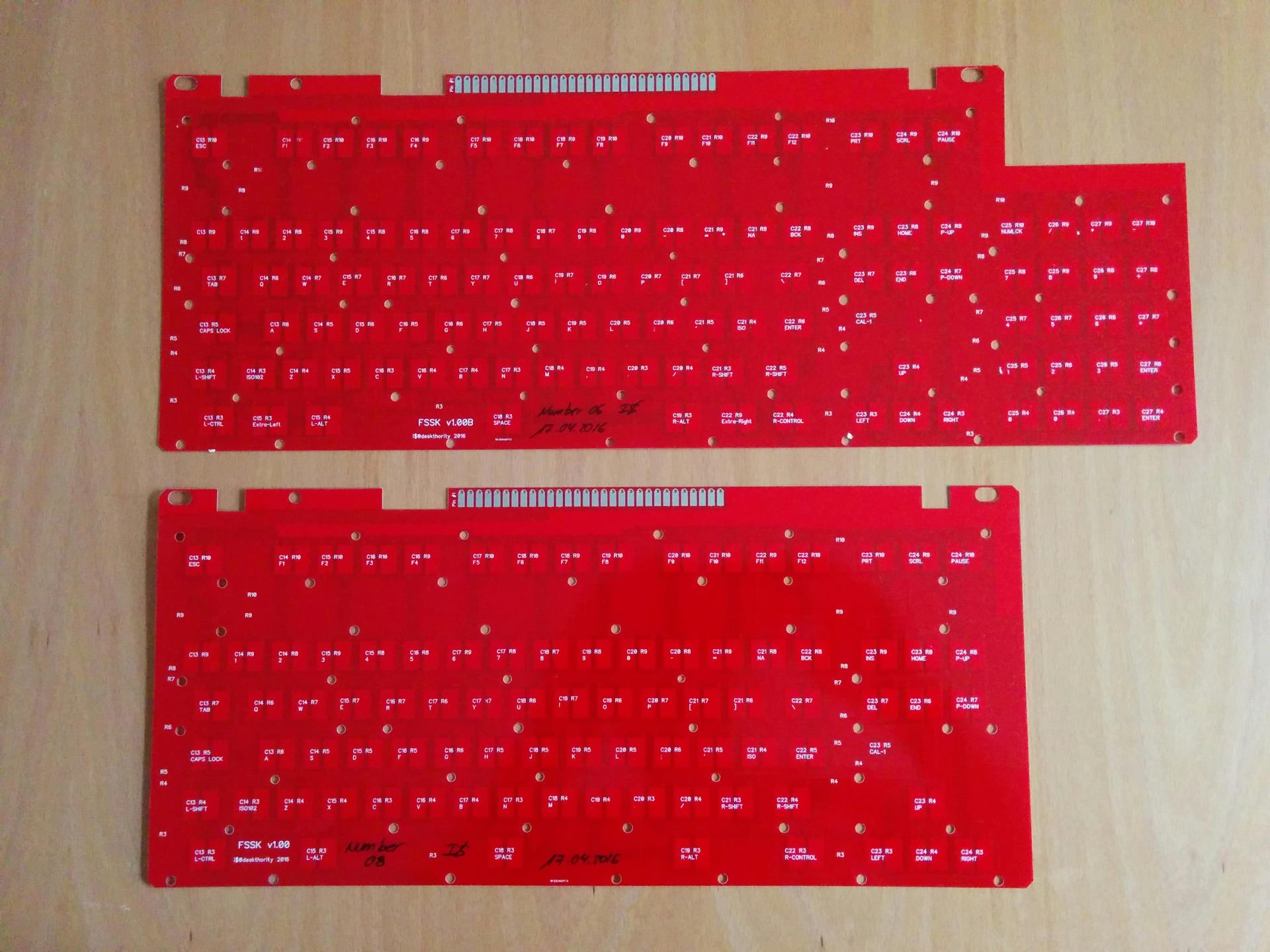
- fsskfext.jpg (241.59 KiB) Viewed 23271 times
Thank you idollar!
Posted: 13 May 2016, 09:12
by idollar
Now I will have to run against Halvar to create the first FEXT
For those interested, notice the extra keys (XMIT) in the bottom row.
Posted: 13 May 2016, 09:15
by idollar
idollar wrote: Now I will have to run against Halvar to create the first FEXT
For those interested, notice the extra keys (XMIT) in the bottom row.
And looking at the picture above, you know now that there are 6 of these prototype FEXTs

One is with Halvar and one with me ...
Posted: 13 May 2016, 12:22
by Halvar
Which bears the question where the other four are ...
I don't see me having enough time on my hands at the moment to build my FEXT fast unfortunately. I will definitely do some testing of the PCB though this weekend.
Posted: 13 May 2016, 13:36
by idollar
Halvar wrote: Which bears the question where the other four are ...
Ready to go to whoever ask for them, once you or I have tested one.
You have the key, and you know that it is call bigfeet mini-GB

Posted: 16 May 2016, 00:33
by Alkhar
Hello idollar
Do we have any news for the flippers / controllers GB ?
Cheers
Alkhar
Posted: 16 May 2016, 08:40
by idollar
Alkhar wrote: Hello idollar
Do we have any news for the flippers / controllers GB ?
Cheers
Alkhar
I have seen some pictures of the flippers that Ellipse has created.
If we would know his source, we could organise it.
Ask him. I have already tried a number of times without a positive result.
Posted: 21 May 2016, 17:38
by idollar
I have a working FEXT prototype without any problem !!!
As it should be, I am typing this post with the first of the FEXT, based on the PCB v1.00b with the XMIT keys (which I have not tested as I do not feel like breaking the case that I have)
I will post this in various threads in which this PCB is discussed.
Posted: 24 May 2016, 02:39
by Techno Trousers
I'm super happy to report that PCB #27, AKA #2b, arrived safely today! idollar really outdid himself on the packaging. It was nestled inside three layers of cardboard--I think the Hulk himself would have had trouble crushing it. Plus it made me hungry as I opened it because of all the Jamon Iberica pictures on the outside box! Mmm... Ham...
Now to find time to actually work on the SSK!.
Thanks, idollar!
Posted: 31 May 2016, 10:15
by tentator
I see I'm not the only one wanting to do something similar.. even if I could already have an unsaver I'd probably not have the courage to do any mod to add winkeys on it..
the navigation keys would be ok by just removing the down key and mapping it to that home in the middle..
so idollar did you have nov a rubber dome unsaver and how does it look to you? doable?
Posted: 13 May 2017, 08:19
by jorgenslee
Sorry to necro this thread, but just wondering if someone has an extra pcb they are willing to let go?
Re: FSSK PCBs (1st round)
Posted: 14 Dec 2020, 04:59
by cheater
Hey, so I just wanted to ask, if we're using our own pcb, what's stopping us from using the model M flippers and springs? I mean they're plastic too, so what's the difference? I assume that the difference in capacitance can still be sensed, even if it doesn't change by the same amount.
Re: FSSK PCBs (1st round)
Posted: 14 Dec 2020, 07:03
by zrrion
The springs would still work, but the plastic is different and would not be sensed at all.
Re: FSSK PCBs (1st round)
Posted: 14 Dec 2020, 07:13
by Weezer
I assume you mean capacitance. The difference in capacitance can be measured in theory since every object has a level of capacitance, but this would likely not work in that application because model m flippers only touch down on one point in the center, whereas model f flippers flap down on a large enough area to measure. The actual area that touches down on a model m flipper is only about 7mm by 3mm
Youd also have to design and calibrate your own controller.
Im not sure why youd want to do that though. Is the idea just to gain N key rollover?
Re: FSSK PCBs (1st round)
Posted: 19 Dec 2020, 04:18
by cheater
Weezer wrote: 14 Dec 2020, 07:13
I assume you mean capacitance. The difference in capacitance can be measured in theory since every object has a level of capacitance, but this would likely not work in that application because model m flippers only touch down on one point in the center, whereas model f flippers flap down on a large enough area to measure. The actual area that touches down on a model m flipper is only about 7mm by 3mm
Youd also have to design and calibrate your own controller.
Im not sure why youd want to do that though. Is the idea just to gain N key rollover?
Two reasons:
1. If you want to turn your M into an F by using a capacitive pcb, but don't have a full compliment of F flippers, you could still use M flippers for some of the keys that are less important to you, and you could get started using your keyboard without delay. You could even just start with all M flippers, while you wait for F flippers to show up / get made / whatever
2. I have a feeling that if the M flippers were directly contacting a rigid pcb, instead of through a soft membrane, the key feel would change. But I don't know for sure. If it does, then this could be an improvement to the key feel without having to sacrifice any F's.
Re: FSSK PCBs (1st round)
Posted: 20 Dec 2020, 08:36
by Wiggles
I know I'm waaaay too late with this one.. Any plans for a second round? Would be awesome!
Cheers
