Page 2 of 2
Posted: 09 Aug 2012, 13:58
by bpiphany
None of the diodes are hooked up. And that is because in the schematic the pins are numbered 1 and 2. And in the footprint they are "numbered" A and C. I'll work on those Poker details..
This footprint placed at the '~' key position is my take on where the mounting holes goes (nothing confirmed). The USB connector I don't think I've measured out actually.
Code: Select all
$MODULE	POKERMOUNT
Po	0	0	0	15	4E0F7A99	00000000	~~
Li	POKERMOUNT
Sc	00000000
AR
Op	0	0	0
T0	0	0	600	600	0	120	N	I	21	N"Ref**"
T1	0	0	600	600	0	80	N	I	21	N"VAL**"
$PAD
Sh	"SLOT"	O	2000	1000	0	0	0
Dr	2000	0	0	O	2000	1000
At	STD	N	0000FFFF
Ne	0	""
Po	-2875	18750
$EndPAD
$PAD
Sh	"SLOT"	O	2000	1000	0	0	0
Dr	2000	0	0	O	2000	1000
At	STD	N	0000FFFF
Ne	0	""
Po	107875	18750
$EndPAD
$PAD
Sh	"SLOT"	O	2000	1000	0	0	0
Dr	2000	0	0	O	2000	1000
At	STD	N	0000FFFF
Ne	0	""
Po	79750	30000
$EndPAD
$PAD
Sh	"SLOT"	O	2000	1000	0	0	0
Dr	2000	0	0	O	2000	1000
At	STD	N	0000FFFF
Ne	0	""
Po	98500	7500
$EndPAD
$PAD
Sh	"SLOT"	O	2000	1000	0	0	0
Dr	2000	0	0	O	2000	1000
At	STD	N	0000FFFF
Ne	0	""
Po	6500	7500
$EndPAD
$EndMODULE	POKERMOUNT
Posted: 09 Aug 2012, 18:00
by Index
Yeah, I figured out and fixed the problem with the diodes a couple of hours after I posted the update. I still need to go verify all the components and make sure they're being wired correctly. As for that Poker Mount, is that for the Mini USB connector?
Posted: 09 Aug 2012, 20:06
by bpiphany
No, those are the screw holes required to attach the PCB to the Poker case.
Posted: 09 Aug 2012, 21:43
by regack
This looks great, Index. I was playing with bpiphany's example files but couldn't figure out where to fit a teensy, mouting the components individually will make it a lot easier... if not making the soldering more... fiddly... Not to get ahead or anything, but I know you can source the $8 ATMEGA32U4 chip pre-loaded with halfkay from PJRC... not sure where you could source one loaded with LUFA...
Posted: 10 Aug 2012, 00:44
by bpiphany
The halfkay preloaded chips are sort of a scam =P The tiny size of the bootloader is nice, but that is all there is to it. If you want to change any hardware settings on the chip, like fuses, you erase the bootloader.
All chips come with Atmel's own bootloader from scratch, and the LUFA bootloader can be flashed to the chip with a serial programmer. The stock bootloader should be fine for all purposes though.
Edit: I just want to add that the "scam" lies in their pricing. The chips are ~$4 if you order 25 of them, and those extra $4 for the bootloader is a bit hefty in my opinion.
Posted: 10 Aug 2012, 02:21
by regack
Thanks for the clarification. I might stick with the Teensy loader since I have some other projects that use Teensys... that said, it's always good to branch out and learn how to use something else... and save some cash for another project.
Posted: 10 Aug 2012, 09:48
by JBert
bpiphany wrote:Edit: I just want to add that the "scam" lies in their pricing. The chips are ~$4 if you order 25 of them, and those extra $4 for the bootloader is a bit hefty in my opinion.
Don't call it a scam then - if it's overpriced, just tell it like it is.
Posted: 10 Aug 2012, 11:57
by bpiphany
You may want to look over the switch placements one more time. These numbers are from my favourite spreadsheet.. All numbers are the X-coordinate relative to 'Esc' in your layout.
Code: Select all
Number:  1.00   1.00   1.00   1.00   1.00   1.00   1.00   1.00   1.00   1.00   1.00   1.00   1.00   1.00   1.00
            0   7500  15000  22500  30000  37500  45000  52500  60000  67500  75000  82500  90000  97500 105000

Tab:     1.50   1.00   1.00   1.00   1.00   1.00   1.00   1.00   1.00   1.00   1.00   1.00   1.00   1.50
         1875  11250  18750  26250  33750  41250  48750  56250  63750  71250  78750  86250  93750 103125

Enter:   1.75   1.00   1.00   1.00   1.00   1.00   1.00   1.00   1.00   1.00   1.00   1.00   2.25
         2813  13125  20625  28125  35625  43125  50625  58125  65625  73125  80625  88125 100313

Shift:   2.25   1.00   1.00   1.00   1.00   1.00   1.00   1.00   1.00   1.00   1.00   1.75   1.00
         4688  16875  24375  31875  39375  46875  54375  61875  69375  76875  84375  94688 105000

Space:   1.50   1.00   1.50   7.00   1.50   1.00   1.50
         1875  11250  20625  52500  84375  93750 103125
Posted: 11 Aug 2012, 08:48
by bpiphany
This is the best I've got on the USB connector. Those are millimetres to the right.
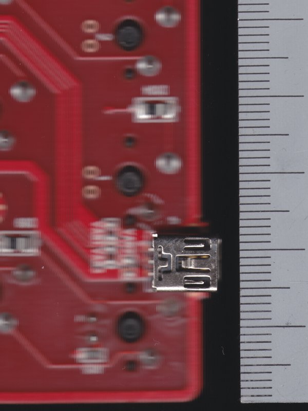
- pokerusb.jpg (54.26 KiB) Viewed 3401 times
Posted: 11 Aug 2012, 23:21
by Index
Bpiphany, freaking baller. I'm so close to finishing this (couldn't have done it w/o you), then off to prototyping.
Posted: 21 Aug 2012, 01:36
by Index
Found a mini usb smt port that I can use with the PCB.
http://www.hirose.co.jp/cataloge_hp/e24000019.pdf
Just need to make a new footprint for it.
Posted: 30 Aug 2012, 20:05
by Index
Not gonna lie, this project is put on hold for awhile. Why? Because Guild Wars 2. Been waiting for that game since 2006 (or whenever it was first announced).
Posted: 30 Aug 2012, 22:52
by JBert
Hmmm... I could sure use a new PCB for the Poker, cause it seems I can't wire up a Teensy dead-bug style to the existing one (the pitch of the controller traces is just too crazy to solder wires one by one).
Please let us know if you want to pick it up again.