Page 2 of 3
Posted: 25 Nov 2013, 19:24
by mashby
matt3o -- you never cease to amaze me. WOW.
Posted: 25 Nov 2013, 19:51
by nourathar
wow, that is great and VERY inspiring; an oldschool technique i've only heard about and it looks very feasible, if armed with zen-monk precision and patience. Those chemicals look about as dangerous as the bleach in my film hand-developing days.
Would also be a great way to be able to have a more freestyle (or ergonomic, if you insist, less square in any case) arrangement of keys ?
J.
Posted: 25 Nov 2013, 19:54
by matt3o
mashby wrote:matt3o -- you never cease to amaze me. WOW.
thank you man

nourathar wrote:Would also be a great way to be able to have a more freestyle (or ergonomic, if you insist, less square in any case) arrangement of keys ?
sure, the good part of custom kb is that you can do whatever you want
Posted: 25 Nov 2013, 22:04
by Muirium
matt3o wrote:if I remember from one of your pictures you have loose wires connecting the rows/cols. my suggestion would be to make the wires very tight. Can you take a close up of your hand-wiring job?
Diode porn!
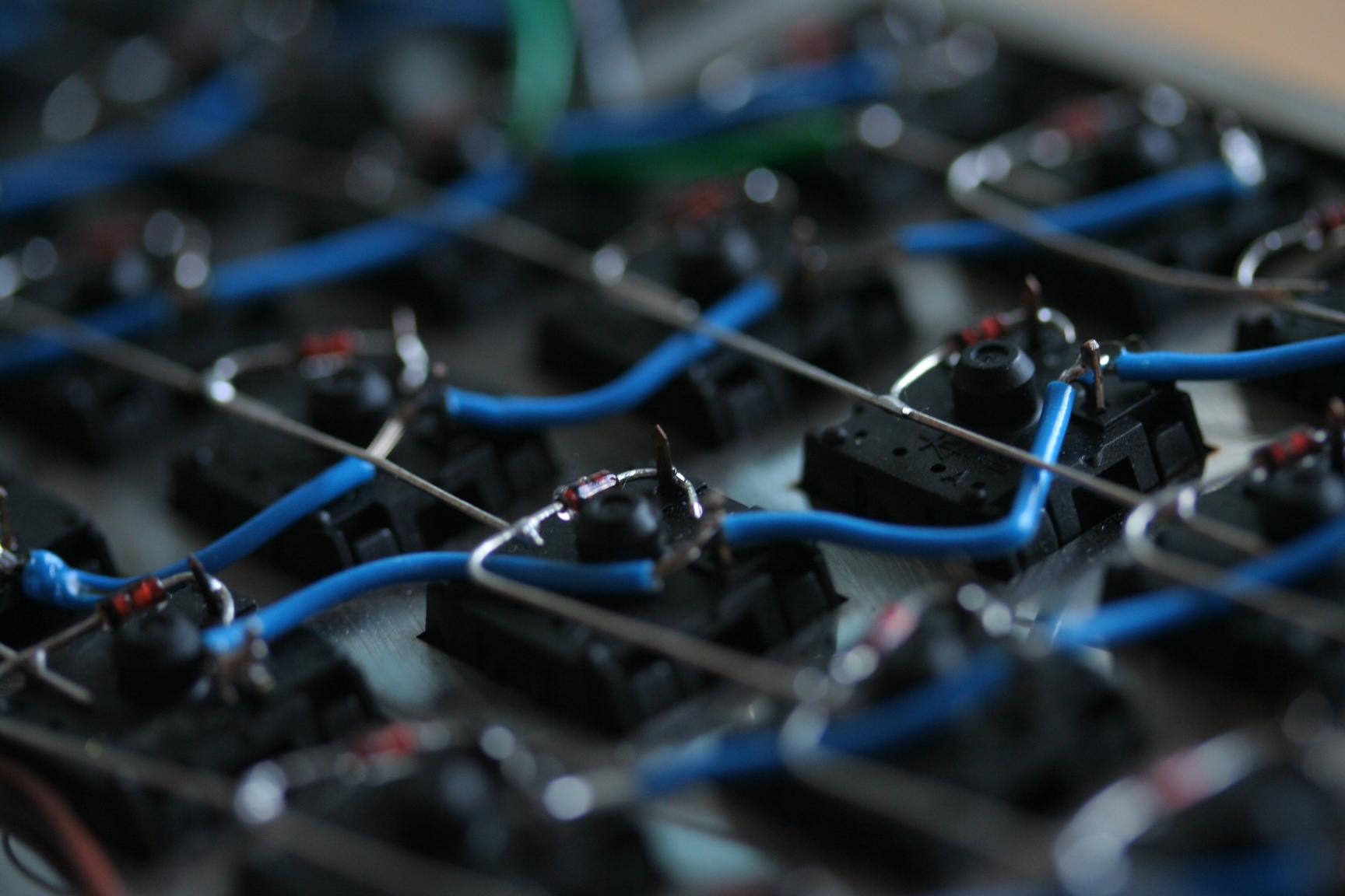
- image-3.jpeg (444.3 KiB) Viewed 6055 times
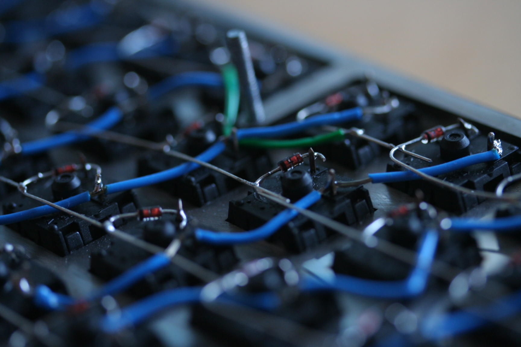
- image.jpeg (448.78 KiB) Viewed 6055 times
Love how a camera can make sloppy work look nice!
And a more informative shot to answer your question:
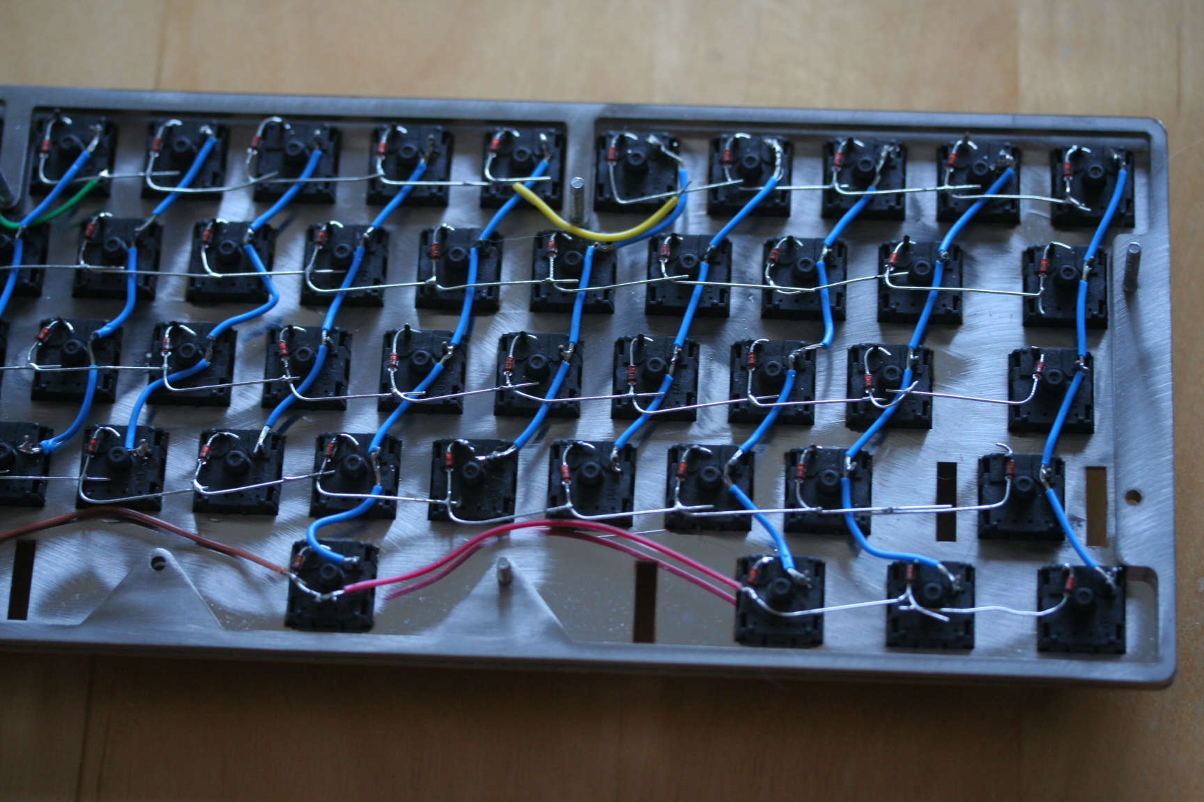
- image-4.jpeg (616.47 KiB) Viewed 6055 times
Posted: 25 Nov 2013, 22:23
by mr_a500
"Diode" and "porn"... I never thought I'd see both those words in the same sentence.
Posted: 25 Nov 2013, 22:27
by Muirium
You don't even want to know what I get up to with a bag of transistors. Those *third* legs, oh my…
Posted: 25 Nov 2013, 23:02
by Vierax
rofl !
You seem to have an expensive camera (or a good skill and the appropriate lens)
Posted: 25 Nov 2013, 23:31
by Muirium
The trick is to shoot looking into reflections. And for arty blur, go wide open with a quick lens. f/2.8 in this case.
More PCB pictures please. Matt's one deserves a spot on the site banner!
Posted: 26 Nov 2013, 00:12
by matt3o
your wiring is not that bad. the wires are okay, the problem is more with the diodes I believe (connections are a bit messy). Also I see some spots were cols go dangerously close to rows.
I would also rewire the yellow one. Use a smaller wire, go under the current matrix down from row 1 to below row 2 and up again to row 1. Cut all wire ends if they are too long (again I see at least a couple of dangerous spots from here). Be sure that the sides and the bottom of the case are well insulated. It might be that a wire shorts on the side and not on the bottom.
If that's not enough you can try to insulate the connections with epoxy glue. If you want you can send it to me and I'll try to review it.
Posted: 26 Nov 2013, 00:24
by Muirium
All good points. I'll redo the yellow wire and get snippy with the loose ends near case edges, etc.
Quite miraculously, it all worked the first time I tested continuity and again when I put it together with the Teensy. So I let my enthusiasm race me on instead of taking my time to finish things off with finesse. Pretty confident I should do it better this time.
As for the Teensy, I'd like to fix it in place really, as the plan is to put Bluetooth components in place down at the back as well. Like your next move in the similarly stepped case HHFox!
Posted: 26 Nov 2013, 11:51
by Ichigo87
you've just made my day, really good idea... I wanted to build my own keyboard without too much tools and i think this diy PCB + wood could be the best way to do it! (i want to build my own CNC for alu and plastic but it is an other story... for an other year...)
Posted: 26 Nov 2013, 12:03
by matt3o
Ichigo87 wrote:(i want to build my own CNC for alu and plastic but it is an other story... for an other year...)
please elaborate, I'm on the same project...
Posted: 26 Nov 2013, 13:06
by Muirium
HaaTa just found your PCB's ancestor.
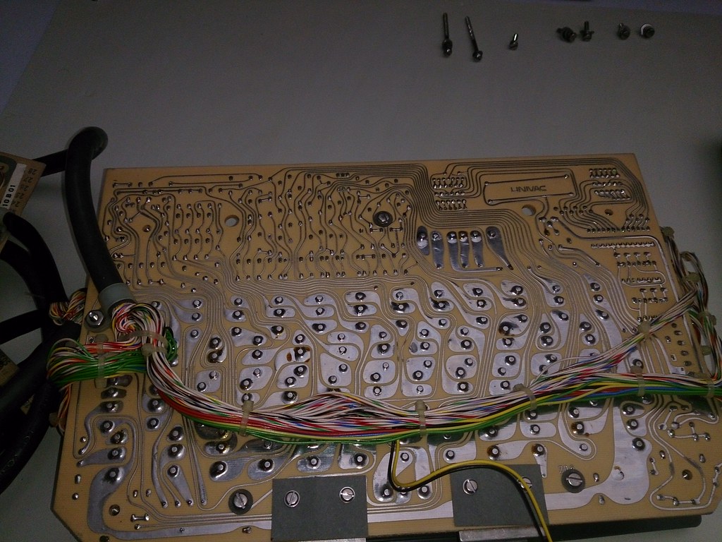
Univac: crazy the old way. Take a look at the switches too.
http://deskthority.net/photos-videos-f8 ... t6918.html
Posted: 26 Nov 2013, 13:40
by Ichigo87
matt3o wrote:Ichigo87 wrote:(i want to build my own CNC for alu and plastic but it is an other story... for an other year...)
please elaborate, I'm on the same project...
I am still at the beginning, i read a lot on french forum, I try to figure out if what i have in mind is duable for a reasonable price (approx 500€). I want it small because i am gonna use it on a desk and i only need to work on max 30cmX30cm pieces (keyboard and arcade stick), i need a box to reduce noise but i don't need extreme precision. Using my dremel can be a plus.
After some research working on wood and acrylic don't seem to need a highly evolved structure but i would like to work on aluminium sheet (for KB plate) and i am not sure if it is possible with a cheap diy CNC. And i also need to learn some CAD basics.
So it is a long time project...
before i would like to try your pcb technique, what did you used to draw the holes accurately on the copper, only pencil and ruler?
Posted: 26 Nov 2013, 14:51
by matt3o
Ichigo87 wrote:matt3o wrote:Ichigo87 wrote:(i want to build my own CNC for alu and plastic but it is an other story... for an other year...)
please elaborate, I'm on the same project...
I am still at the beginning, i read a lot on french forum, I try to figure out if what i have in mind is duable for a reasonable price (approx 500€). I want it small because i am gonna use it on a desk and i only need to work on max 30cmX30cm pieces (keyboard and arcade stick), i need a box to reduce noise but i don't need extreme precision. Using my dremel can be a plus.
After some research working on wood and acrylic don't seem to need a highly evolved structure but i would like to work on aluminium sheet (for KB plate) and i am not sure if it is possible with a cheap diy CNC. And i also need to learn some CAD basics.
So it is a long time project...
from my little experience, an alu frame is mandatory for precision works.
Ichigo87 wrote:before i would like to try your pcb technique, what did you used to draw the holes accurately on the copper, only pencil and ruler?
I printed a CAD drawing with the to-the-micron position of the holes. Then with a hand drill I made a small dent and lastly with a standard drill I made the holes.
Posted: 26 Nov 2013, 15:02
by Muirium
matt3o wrote:I printed a CAD drawing with the to-the-micron position of the holes.
Before our plates went to the laser cutter, I tried this for visualisation's sake but found a 1:1 scale impossible to achieve. You're printing directly from inside DraftSight or Inkscape? I had to go via PDF, which threw the scale off.
Posted: 26 Nov 2013, 15:09
by matt3o
Muirium wrote:matt3o wrote:I printed a CAD drawing with the to-the-micron position of the holes.
Before our plates went to the laser cutter, I tried this for visualisation's sake but found a 1:1 scale impossible to achieve. You're printing directly from inside DraftSight or Inkscape? I had to go via PDF, which threw the scale off.
I had the same problem. My solution was DXF > PDF > SVG. From inkscape I set the width == the real board width in mm. It turned out perfectly aligned.
Posted: 26 Nov 2013, 22:09
by bearcat
I've got a shapeoko CNC -- some of the folks on the forums have used it to cut aluminium without any trouble; i'm waiting for a new set of x-axis plates & some endstops before i try any aluminium.
Another affordable CNC kit i've heard really good things about is Lobo CNC. Very rigid frame, definitely capable of doing alu & brass. A local hackerspace has one and gets some really nice results.
Posted: 26 Nov 2013, 23:15
by matt3o
ooh the shapeoko seems nice! thanks for sharing!
edit: I double checked the shapeoko, it doesn't have the resolution I'm looking for... I'm afraid that to get something serious you can't go under 1500 euros. Anyway a very nice project nonetheless
Posted: 27 Nov 2013, 14:30
by Ichigo87
bearcat wrote:I've got a shapeoko CNC -- some of the folks on the forums have used it to cut aluminium without any trouble; i'm waiting for a new set of x-axis plates & some endstops before i try any aluminium.
Another affordable CNC kit i've heard really good things about is Lobo CNC. Very rigid frame, definitely capable of doing alu & brass. A local hackerspace has one and gets some really nice results.
That's look like a perfect christmas gift, too bad i live in France (shipping = 137 USD).
Posted: 27 Nov 2013, 15:15
by matt3o
Indeed if it were in EU I might have considered it. Even though it seems there's a distributor in UK
Posted: 27 Nov 2013, 16:17
by Ichigo87
matt3o wrote:Indeed if it were in EU I might have considered it. Even though it seems there's a distributor in UK
Do you speak about Markerslide?
This is a really interesting CNC, i need to read more about it but it seems enought to make keyboard and arcade stick with wood, plastic and thin aluminium sheets.
Posted: 27 Nov 2013, 16:29
by matt3o
Ichigo87 wrote:matt3o wrote:Indeed if it were in EU I might have considered it. Even though it seems there's a distributor in UK
Do you speak about Markerslide?
This is a really interesting CNC, i need to read more about it but it seems enought to make keyboard and arcade stick with wood, plastic and thin aluminium sheets.
sorry, forgot the link
http://makerslideeurope.com/
Posted: 27 Nov 2013, 17:03
by thefish
There's a better method than drawing everything by hand. It is called "Laser Ironing", and is available with common materials at home.
Basically you'll need a laser (that's very important) printer, glossy magazine cover and clothes iron.
1) Set your printer to maximum toner expense and print your pre-designed PCB on the glossy cover page. Just turn all toner-saving settings off and use maximum boldness. Beware, your PCB scheme must be printed MIRRORED.
2) Clean your metal plate with degreaser and polish it if needed.
3) Place printed sample over your metal plate (printed side DOWN), and put a thin piece of cloth (or just a thick paper sheet) over it. Carefully iron over this sandwich (temperature must be in range from mid to high, depends on toner quality). Congratulations, now your PCB layout is transferred from glossed page to metal.
4) If some toner pieces have come off during ironing - just draw these with permanent marker.
5) Profit! Continue with etching.
This method allows even creation of small series of custom PCBs with somewhat high precision, and is widely used by electronics enthusiasts in Russia.
Link with detailed description and video:
http://cxem.net/master/45.php (Russian!)
Posted: 27 Nov 2013, 17:16
by Muirium
That's the kind of smartly lazy process I can believe in!
Re: CNC. I can do any UK proxying you guys need. I'm keen to see you get started on this so I can join in when you're making good stuff!
Posted: 27 Nov 2013, 17:24
by matt3o
I tried the laser printer thing, but it didn't work for me (it didn't last the acid process). But I'm sure I'm doing something wrong.
thanks Muirium! problem is that it's out of stop ATM
Posted: 27 Nov 2013, 21:13
by bearcat
matt3o wrote:edit: I double checked the shapeoko, it doesn't have the resolution I'm looking for... I'm afraid that to get something serious you can't go under 1500 euros. Anyway a very nice project nonetheless
O_O what kind of resolution are you talking about? The shapeoko can get to sub-.1mm tolerances without any trouble. I don't know if i'd use it to route PCBs, but it's definitely capable of milling keyboard trays. It almost gets easier with alu because you run at a much slower feedrate.
Anyway, my goal for the holidays is to get the shapeoko cutting some alu trays, so i'll report back & you can decide

Edit: i should say, what kind of resolution are you shooting for?
Posted: 27 Nov 2013, 21:14
by Muirium
And caps. For the love of cod, make some engraved caps!
Posted: 27 Nov 2013, 21:16
by Medowy
Damn!! You definitely nailed it!!
Posted: 02 Dec 2013, 12:33
by matt3o
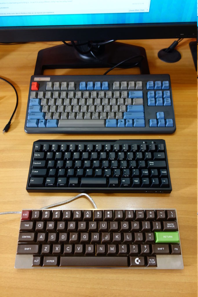
Keyboard finally finished!
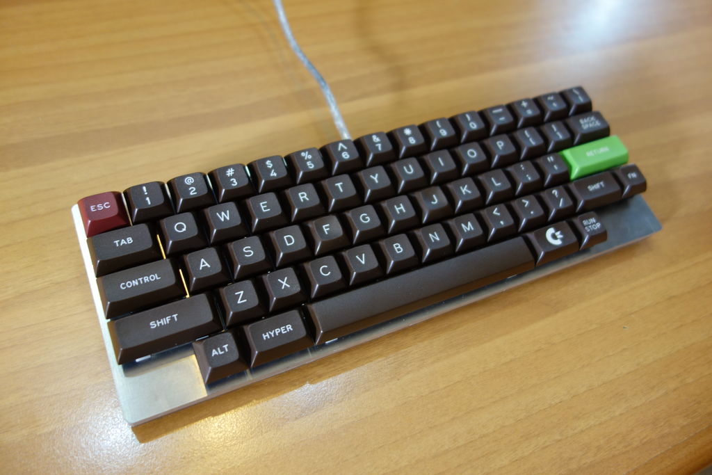
Just a pinch smaller than Filco Minila Air!
I'm now trying to get used to the HHKB layout (with some important variations actually).
All switches are MX Blue except for the right FN which is Red. After a while working on it I found a little tiring to pinky-press it, so I softened it a bit with a MX Red.
Home/End are on < and > instead of L and .
It feels much more natural to me this way.
The Hyper key is actually a second FN key. very useful to reach the function layer with the left hand. The C64 is for firmware update. Everything else is very close to the HHKB.
This is by far the most complicated, long to build, swear-prone, keyboard I've ever build... But it's also definitely the best one!
Stay tuned for the next custom keyboard
(I've got an ALU poker case so I might end up doing something with it)