Awesome Ellipse. And funny you should mention it. I’ve been working on a DIY solenoid solution. But great to have an option delivered with the keyboards.

I have powered the solenoid and buzzer in my board with a simple circuit hooked up to the xwhatsit controller.
This might not be the best or the only way for doing this, but it works for me. Have prepared a little writeup for how I did make it work and what is needed. Figured someone would be interested. This could easily be adapted to other boards, and even teensys running QMK.
The circuit is made just from reading up on solenoids. I take no responsibility for your keyboard or computer. Modify and add a solenoid+buzzer at your own risk.
Here is the shematics for it all.
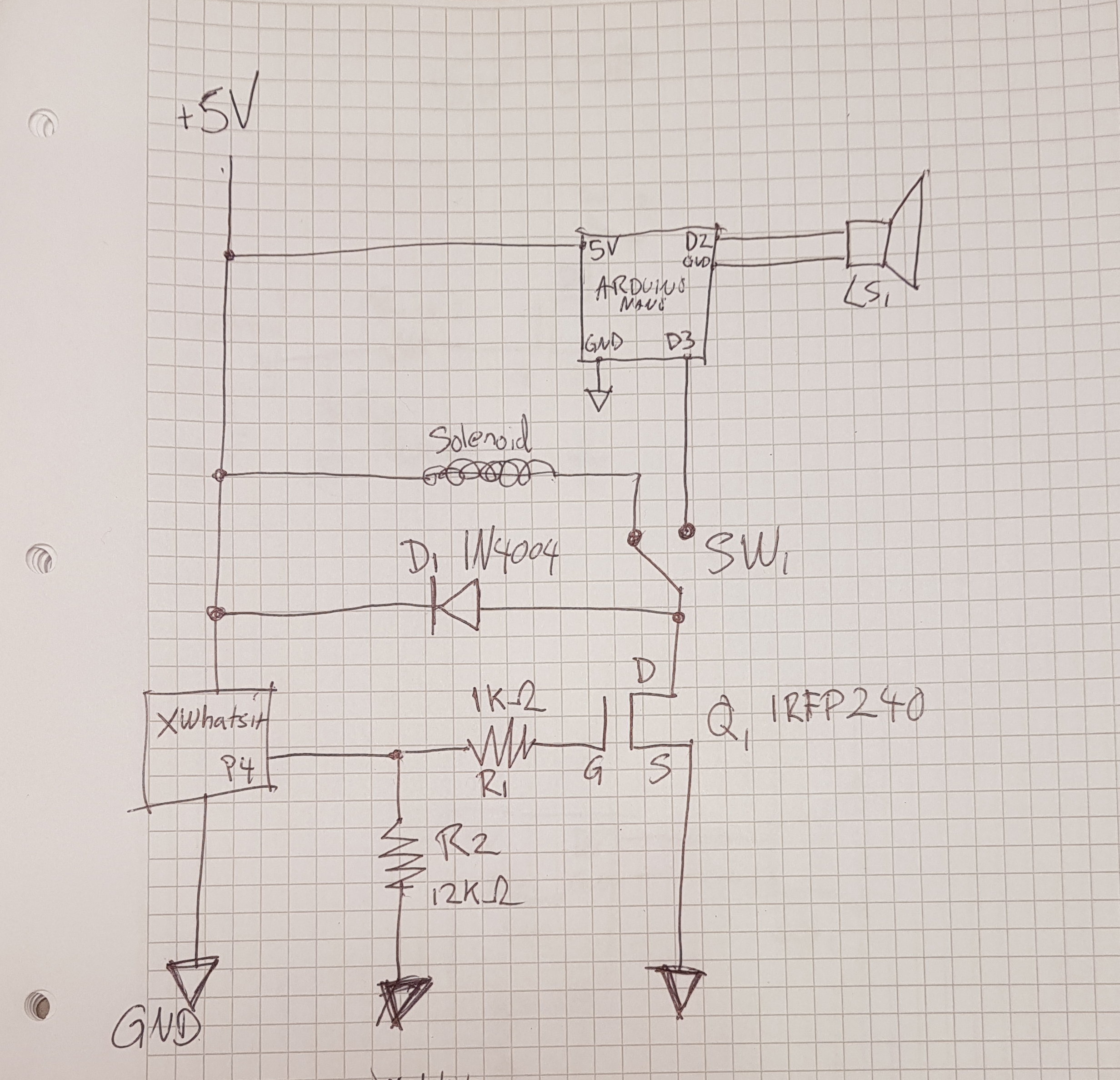
- schematics.jpg (3.19 MiB) Viewed 8641 times
There are a lot of ways to work out a driving board. Xwhatsit’s driver board is the obvious choice, @kmnov2017 used a relay that’s easy and elegant, and should work just as good. I have chosen a mosfet instead of a relay, because it’s what I had in hand. And I prefer a quicker switching circuit for a current hungry relay with moving parts.
In my schematics I use a N-channel mosfet as a relay to switch the low current from the xwhatsit pin #4 with the higher current off the USB.
Parts here are chosen for what I had in my stash. Beeing an DIY guy, I have a few piles of started projects, and projects I never got around to even start. The mosfet I found in a bin of leftovers from several amplifier builds.
Bill of material in this project:
Q1 N-channel MOSFET IRFP240
D1 Diode IN4004
R1 Resistor 1K Ohm
R2 Resistor 12k Ohm
SW1 Switch SPDT
Solenoid
https://www.ebay.com/itm/0837L-06K-6V-0 ... 1967978003
Arduino Nano
LS1 Speaker 50ohm 0,5w
PCB Experiment type. Point-to-point soldering would also work.
You will need a soldering iron and some hook up wires as well.
The solenoid I used here is specced at 6v, but works fine on the 5V provided by USB. It draws around 110mA at 5V (measured) and is a tight fit.
There might be other solenoids that could work with this circuit, but not all will fit in the keyboard. You are looking for a push/pull with the operating voltage around 5V and a short throw. If you stay within the limits of the USB standard current wise, 500mA you should be fine. Boosting the voltage is also fine for more oomph or for a higher voltage solenoid. But take care to calculate the power usage.
For Q1 almost any N-channel mosfet should do, I simply choose what I had on hand and it’s likely overkill for this application. The same goes for D1. The Diode provides circuit protection if there is a build up of stored energy in the solenoid.
The R1 is for protecting the xwhatsit controller, it limits the current going to the gate of Q1. And in case of circuit failure, it will hopefully help not to fry your keyboard controller. Any value from 100ohms to 1k ohms would work here.
R2 is not really necessary, but it should help keep the solenoid from going off when not triggered, choose a value around 10k.
Building the circuit board from an experiment PCB should be straight forward, one could fan out the components as you like. I tried to make it compact.
If you want the buzzer, an arduino nano is a neat little programmable driver. If not - you won’t need the switch, arduino or the speaker. Just hook up the mosfet drain directly to the solenoid and diode. Leave out the solenoid and switch if you only want the buzzer.
I am not going in depth here on programming the arduino, but here is the code I used for mine. Frequency is totally tuneable if you want another tone. One could even program the board to play different tunes every other keypress. I tried to add a boot tune to my board, but it was mostly annoying..
I settled at 550Hz, it gives a somewhat deeper sound than the buzzer originally in the IBM 4704. Tweak as you like
Code: Select all
int buttonPin;
const int buzzer = 2; //speaker on pin 2
void setup()
{
  buttonPin = 3; //signal from mosfet on pin 3
  pinMode(buttonPin, INPUT_PULLUP);
  pinMode(buzzer, OUTPUT);
}

void loop()
{
  if(digitalRead(buttonPin) == LOW)
  {
  tone(buzzer, 550); // Freqency
  delay(20);        // Beep lenght
  noTone(buzzer);     // Stop signal
  }

}
Then simply have one of the outputs from the switch go to D3 on the arduino, and hook up the speaker to the D2 and ground(GND).
The little speaker I used came from a car parking sensor. You can probably use whatever fits inside. The bigger the better.
Hooking up to the keyboard is done at the xwhatsits controller expansion header.
Pin 4 carries the signal to the driver board.
Pin 6 is the GND
Pin 1 is 5v straight off the USB port. This is identified on the PCB by having a square solder mask. (GND opposite corner)
For mounting the solenoid inside the chassis I drilled(sorry Ellipse!) two holes and secured it with a small zip-tie.
I tried to make it work with the hole already there for the extended feets, but that would mean a screw head sticking out on the underside making all kinds of scratch to my desks. The zip tie is thin enough on the underside to not extend higher than the cork feet. So it won’t make the board wobble.
A strong double sided tape might do for securing the solenoid, but that could loosen over time so I went with a little more invasive approach.
Speaker mounts itself with its own magnet to the steel assembly. So just slap it in there and you will be fine.
By taking the cable out the square recess, you can fit the switch in the round hole where the cable normally goes without any drilling. Locks in place without the nut.
For the xwhatsit software I have settled at 45 ms extend time and 90 ms retract time. Might tune this some more.