Have there ever been any attempts to make MX mount sliders for a Model M?
Posted: 03 Jan 2023, 06:39
And, if so, did they ever go anywhere?
mechanical keyboard authority
https://ns1.deskthority.net/
It's a big thread. There may be more about this sub-project in there. But Lot Lizard himself has been gone for years now.lot_lizard wrote: 20 May 2016, 18:00 Again, the first step in all of this is getting the drop-in replacement working for both the 84 and 101-key M's, but am using this thread as part of a bunch of stuff we might like to do as part of the larger project (unless there are objections thinking it will make it messy).
The following is the original rendering for the Cherry MX buckling spring adapter. I had originally put some of this in matt3o's buckling spring with a cherry on top thread, but would like to just keep track of the progress here, since I view it as another step in this larger goal. Apologies to those that have already seen.
More renderings of the same stem from different angles
Backside laying flat on the desk
Inside the buckling spring stem from the bottom
Cross Section to help visualize the mechanics
The above would account for all the standard keys, but there are 5 special keys (Spacebar, Capslock, Shift(s), etc) on the 84 key M, and 2 additional on the 101-key. I have ordered a Cherry board to take some measurements from (ironically I don't currently own a single Cherry key), and will progress forward when that arrives.
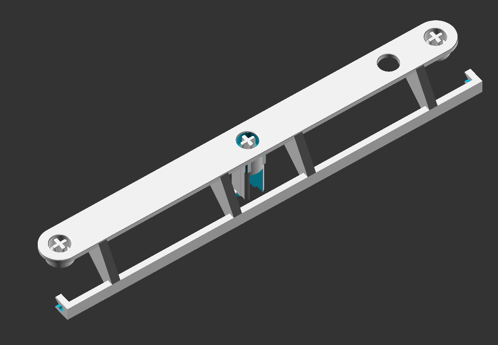
But using the dimensions of the spacebar from our wiki, have constructed the spacebar adapter (by far the most complex) ahead of time. I am confident it will be very close, but will likely add a sleeve to take advantage of the spare barrel blank on the M (testing will tell for sure)
More renderings of the same stem from different angles
Front looking upward
Front looking downward
Profile (the wire clips are there, but not rendered well by the visual)
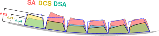
We discussed a potentially making the plates flat as part of this longer term project (after the drop-in replacement portion is complete), and have NO IDEA if that is even feasible yet without testing... but even if it doesn't, the following is a set of renderings that were put together to show what the Signature Plastics key profiles would be on the curved plane of the M. Looks promising... The blue outline shows the model M/F cap profile as it exists today
And the following shows the progression of how this cap profile "simulation" was constructed
This is the original:
This is the original in relation to the IBM barrel assembly curve (300mm radial bend for the angle):
And this is the result of the two merged:
This would be the actual rotation of the backplate as it sits in the case. It is possible that Cherry boards sit on an incline in the case as well. I have no idea... don't own one:
And lastly, with IBM keycap profiles in Blue:
I currently have a working prototype for the standard key that I have been using for a few of weeks now, but have sent off for another print with VERY slight changes to the actuation point. The order is FINALLY scheduled to ship from Shapeways on 5/26 (3+ week delay on Acrylate), and I will take detailed pics (possible video) then.
EDIT: Flat plate testing!!!
Disclaimer
I can tell you that before you read any of this, there are two obvious things that would need to occur to make the flat plate version OPTIMALAgain... enough yik-yak... time for photos
- Barrels reduced - The barrel would need to be shortened on the Y-axis (assuming you are sitting in front of the keyboard, and the width is the X) by ~.5mm per barrel, and the rows would need to be tightened to reflect that change. By flattening the plate, we are increasing the space in between the rows since the keys sit closer to the origin of the radial bend than does the backplate. The great part, the barrels can lose a full ~1mm from the front (~.5mm from the back) before the flipper would need to be altered in any way. This change needs to happen, and should to be in our original barrel order (even for the drop-in since it impacts nothing) as it prepares us for the future, and we continue to have a single barrel mold (flat or curved plate)
- Flipper pitch flattened - It also stands to reason that the pitch of the flipper should be flattened to contact the PCB pad more evenly. Having said that, I first tested the PCB flat before ever bending, and all keys easily registered. More testing will need to occur here before it is worth declaring a need, but a flipper that is in between the two ending pitches is probably ideal (again... one flipper to rule them all, regardless of plate radius)
Cold Rolled Steel A366/1008 0.048 inch (~1.25mm) (18 gauge). I planned on priming and painting, so I selected a higher carbon steel than stainless to provide higher "strength"
I don't currently have the PCB soldered to the controller yet to prove functionality, but aside from the ~.5mm row gap, this compressed contraption is incredible. The keys feel phenomenal with zero noticeable plate flex, even the keys in the middle make the same consistent "ping". I think I can confidently say at this point (knowing that the flipper test worked on the flat PCB before I bent it... with every key registering perfectly...) this would work if it is desirable for Cherry adapters later. Any additional noise or plate flex (I notice none, and I type HARD) can EASILY be accounted for with additional metal gauge or pressed seams (like the Beamspring). I have zero question this works (assuming the flippers register, and I would be willing play Vegas on that one if someone feels lucky
- Bare Plates Received from Big Big Saw
Top plate only, preconditioned (no sanding or deburring)
What big boys use to countersink and deburr circular holes. With a press, it makes short even work- Plates primed with a metal etching primer (to allow for handling)
Top plate primed with a HVLP paint gun after processing (sanding and countersink)
Bottom plate primed- Foam, Barrels, Flippers added
Foam, barrels, flippers, and stabilizers in place
- Compression of the plates with keys added
Everything in place with clamp compression (note... 4 points of compression is WEAK compared to what our end result would be)
Previously mentioned gap that would need to be lessened by ~.5mm per row). I am SUPER excited about the doors this testing has opened
EDIT: The Shapeways order including the Acrylate keystem adapters, space bar adapter (the reason the whole order was postponed), flippers, barrels, and barrel stabilizers will be shipped out tomorrow (6/1). I should have an update some time this weekend after returning from my work trip
This is why I love DT.Muirium wrote: 03 Jan 2023, 18:02 Here we go, this was the most promising one: Lot Lizard explored MX mount Model M sliders as part of his audacious Model MF project:
It's a big thread. There may be more about this sub-project in there. But Lot Lizard himself has been gone for years now.lot_lizard wrote: 20 May 2016, 18:00 Again, the first step in all of this is getting the drop-in replacement working for both the 84 and 101-key M's, but am using this thread as part of a bunch of stuff we might like to do as part of the larger project (unless there are objections thinking it will make it messy).
The following is the original rendering for the Cherry MX buckling spring adapter. I had originally put some of this in matt3o's buckling spring with a cherry on top thread, but would like to just keep track of the progress here, since I view it as another step in this larger goal. Apologies to those that have already seen.
More renderings of the same stem from different angles
Backside laying flat on the desk
Inside the buckling spring stem from the bottom
Cross Section to help visualize the mechanics
The above would account for all the standard keys, but there are 5 special keys (Spacebar, Capslock, Shift(s), etc) on the 84 key M, and 2 additional on the 101-key. I have ordered a Cherry board to take some measurements from (ironically I don't currently own a single Cherry key
But using the dimensions of the spacebar from our wiki, have constructed the spacebar adapter (by far the most complex) ahead of time. I am confident it will be very close, but will likely add a sleeve to take advantage of the spare barrel blank on the M (testing will tell for sure)
More renderings of the same stem from different angles
Front looking upward
Front looking downward
Profile (the wire clips are there, but not rendered well by the visual)
We discussed a potentially making the plates flat as part of this longer term project (after the drop-in replacement portion is complete), and have NO IDEA if that is even feasible yet without testing... but even if it doesn't, the following is a set of renderings that were put together to show what the Signature Plastics key profiles would be on the curved plane of the M. Looks promising... The blue outline shows the model M/F cap profile as it exists today
And the following shows the progression of how this cap profile "simulation" was constructed
This is the original:
This is the original in relation to the IBM barrel assembly curve (300mm radial bend for the angle):
And this is the result of the two merged:
This would be the actual rotation of the backplate as it sits in the case. It is possible that Cherry boards sit on an incline in the case as well. I have no idea... don't own one:
And lastly, with IBM keycap profiles in Blue:
I currently have a working prototype for the standard key that I have been using for a few of weeks now, but have sent off for another print with VERY slight changes to the actuation point. The order is FINALLY scheduled to ship from Shapeways on 5/26 (3+ week delay on Acrylate), and I will take detailed pics (possible video) then.
EDIT: Flat plate testing!!!
Disclaimer
I can tell you that before you read any of this, there are two obvious things that would need to occur to make the flat plate version OPTIMALAgain... enough yik-yak... time for photos
- Barrels reduced - The barrel would need to be shortened on the Y-axis (assuming you are sitting in front of the keyboard, and the width is the X) by ~.5mm per barrel, and the rows would need to be tightened to reflect that change. By flattening the plate, we are increasing the space in between the rows since the keys sit closer to the origin of the radial bend than does the backplate. The great part, the barrels can lose a full ~1mm from the front (~.5mm from the back) before the flipper would need to be altered in any way. This change needs to happen, and should to be in our original barrel order (even for the drop-in since it impacts nothing) as it prepares us for the future, and we continue to have a single barrel mold (flat or curved plate)
- Flipper pitch flattened - It also stands to reason that the pitch of the flipper should be flattened to contact the PCB pad more evenly. Having said that, I first tested the PCB flat before ever bending, and all keys easily registered. More testing will need to occur here before it is worth declaring a need, but a flipper that is in between the two ending pitches is probably ideal (again... one flipper to rule them all, regardless of plate radius)
Cold Rolled Steel A366/1008 0.048 inch (~1.25mm) (18 gauge). I planned on priming and painting, so I selected a higher carbon steel than stainless to provide higher "strength"
I don't currently have the PCB soldered to the controller yet to prove functionality, but aside from the ~.5mm row gap, this compressed contraption is incredible. The keys feel phenomenal with zero noticeable plate flex, even the keys in the middle make the same consistent "ping". I think I can confidently say at this point (knowing that the flipper test worked on the flat PCB before I bent it... with every key registering perfectly...) this would work if it is desirable for Cherry adapters later. Any additional noise or plate flex (I notice none, and I type HARD) can EASILY be accounted for with additional metal gauge or pressed seams (like the Beamspring). I have zero question this works (assuming the flippers register, and I would be willing play Vegas on that one if someone feels lucky
- Bare Plates Received from Big Big Saw
Top plate only, preconditioned (no sanding or deburring)
What big boys use to countersink and deburr circular holes. With a press, it makes short even work- Plates primed with a metal etching primer (to allow for handling)
Top plate primed with a HVLP paint gun after processing (sanding and countersink)
Bottom plate primed- Foam, Barrels, Flippers added
Foam, barrels, flippers, and stabilizers in place
- Compression of the plates with keys added
Everything in place with clamp compression (note... 4 points of compression is WEAK compared to what our end result would be)
Previously mentioned gap that would need to be lessened by ~.5mm per row
EDIT: The Shapeways order including the Acrylate keystem adapters, space bar adapter (the reason the whole order was postponed), flippers, barrels, and barrel stabilizers will be shipped out tomorrow (6/1). I should have an update some time this weekend after returning from my work trip