Page 1 of 2
Cherry G80-1000HFD LED relocation + acrylic case
Posted: 02 Jul 2012, 17:34
by Half-Saint
G80-1000HFD Rev.: 02
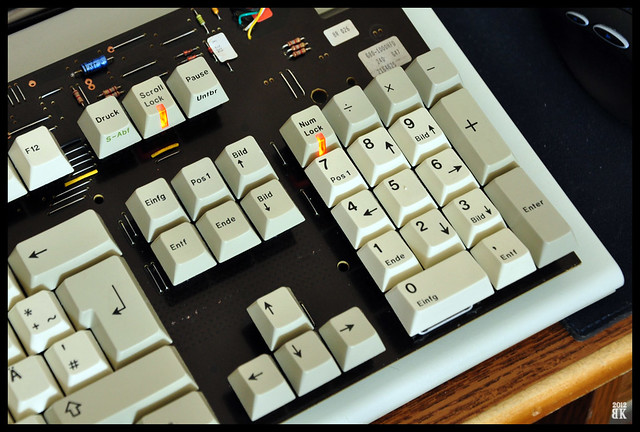
Here is my latest 'project': LED relocation! I got the inspiration from this
Adding LED's on a SSK. I thought maybe I could move the LEDs from their classic 'cluster of three' position to under the caps like G80-1501 or G80-9009.
First I thought that I'll have to hardwire the LEDs but after seeing the PCB, I knew there was an easy way. It appears that Cherry was using the same PCB for diff. model boards which is great news for me


I speculated that I should be able to remove the jumper, remove the old LED, fill the holes with solder and place a LED inside the switch:


Of course this didn't work at first! I found out that the LD2 solder pads weren't connected! I needed three 'bridging wires' to fix this but thanks to Cherry, it wasn't a problem:

Caps Lock works! Now I have to relocate Num Lock and Scroll Lock LEDs next
EDIT: jut finished the mod. You can see where I removed the original LEDs and added two more bridging wires. For the last two I used two wires from an old Cherry I tossed but kept the PCB. I think it looks better this way. When I have the time I'll replace the other three as well.
While doing this mod I damaged one of the switches and it doesn't click anymore. I pressed down on the leafs while extracting the stuck jumper from the switch. Is there any way to fix this?

The end (almost)

Posted: 02 Jul 2012, 18:07
by dirge
Great work mate
(also check your messages)
Posted: 02 Jul 2012, 20:50
by Half-Saint
Thanks!
As soon as I finish the whole board, I'll be posting more pictures.. with keycaps on
Posted: 03 Jul 2012, 11:45
by Half-Saint
Question:
the LED diode I used is too bright. Default resistors are 330ohm. The replacement diode has a forward voltage of 1.8-2V and forward current of 20mA.
Does anyone know the forward voltage of default Cherry green diodes? How do I figure whether the resistors and diodes are in parallel or series on the PCB without trying to draw everything on a piece of paper?
Posted: 03 Jul 2012, 11:52
by off
No clue, big paper fan myself.
But a standard black marker could prove to be all you need anyhow
(just make a stripe or two on the led, only in perfect darkness you'll spot what side has become darker by looking at the light hitting the wall in what is no longer a circle)
Posted: 03 Jul 2012, 11:54
by Half-Saint
I'm just worried about applying too much voltage to the diode which will make it brighter but also quicker to die

Posted: 03 Jul 2012, 12:37
by fossala
Nice work there.
Posted: 03 Jul 2012, 13:18
by off
Well firstly, I'm not quite getting what you're sketching; but I'd say just try a higher res (or if it's stuck on the board, drop an extra res in series with the led somewhere, presumably on the spot of one of those bridges).
Again, marker will save the day, if combined with paper.

Oh, forgot to add, it really was time someone attempted this mod; definitely approved/appreciated!

Posted: 03 Jul 2012, 13:35
by Half-Saint
Here's the finished board:
off wrote:Well firstly, I'm not quite getting what you're sketching; but I'd say just try a higher res (or if it's stuck on the board, drop an extra res in series with the led somewhere, presumably on the spot of one of those bridges).
Again, marker will save the day, if combined with paper.
Oh, forgot to add, it really was time someone attempted this mod; definitely approved/appreciated!
You mean nobody tried it until now?
Well, I might add another three resistors as I have 330ohm spares.
Posted: 03 Jul 2012, 13:40
by kint
I like your choice of colour. Big fan of orange illumination myself, and the colour those came out through the windows of the cap is just right. Red LEDs I take it ?
Also you might want to post the boards/PCB revision so people can refer to that when estimating whether a bridge wire is needed or not. Its a 1000 board that much I could spot...
Posted: 03 Jul 2012, 13:45
by Soarer
The forward voltage is probably close to 3V for the green LEDs, but also your replacement LEDs may well be more efficient. You might find you only need to run them at a few mA - perhaps adding 1kΩ or 2kΩ resistors.
Posted: 03 Jul 2012, 13:52
by Half-Saint
kint wrote:I like your choice of colour. Big fan of orange illumination myself, and the colour those came out through the windows of the cap is just right. Red LEDs I take it ?
Also you might want to post the boards/PCB revision so people can refer to that when estimating whether a bridge wire is needed or not. Its a 1000 board that much I could spot...
The LEDs are orange although it doesn't quite show in the pictures.
Thanks for the hint, I fixed the description
Posted: 03 Jul 2012, 14:53
by CeeSA
Tenkey is still there, cut it off!
Posted: 03 Jul 2012, 15:54
by Half-Saint
CeeSA wrote:Tenkey is still there, cut it off!
Maybe some other time, when I learn how to cut and glue back together the case
Posted: 03 Jul 2012, 15:55
by off
Half-Saint wrote:You mean nobody tried it until now?
Not that I'm aware of, no. The thought had crossed my mind way before signing up, but no mod posts to that extent ever crossed my path..
Beautiful.
What did you end up using resistor-wise?
Downside to TKLing that board, would be losing the num-lock led

Posted: 03 Jul 2012, 15:58
by Half-Saint
off wrote:Half-Saint wrote:You mean nobody tried it until now?
Not that I'm aware of, no. The thought had crossed my mind way before signing up, but no mod posts to that extent ever crossed my path..
Beautiful.
What did you end up using resistor-wise?
Downside to TKLing that board, would be losing the num-lock led
Thank you. Cherry made this a very easy job. I assume the same PCB was used in G80-1501 which already has the LEDs installed under the keys.
I left the default resistors (330ohm) as they were. I'm thinking of adding extra resistors in place of the bridging wires but not today
I'm not going to cut this particular board. I have one more G80-1000 with crap switches that I'm gonna try converting to TKL later this month. If it turns out alright, I can replace the switches and voila!
Posted: 04 Jul 2012, 10:24
by Half-Saint
1. I tried two 330ohm resistors in series and the LEDs were just as bright. Reverted to how it was.
2. Replaced one of the existing 330ohm resistors with a 1.8k one and again, the same brightness! WTF? Nearly destroyed one of the solder pads in the process.. will probably leave the big resistor there because I'm afraid I might wreck the solder pad completely, if I try to remove it.
3. Replaced the remaining two 330ohm resistors with 1.8k and still no difference. Must be those pesky high brightness LEDs.
off wrote:But a standard black marker could prove to be all you need anyhow
(just make a stripe or two on the led, only in perfect darkness you'll spot what side has become darker by looking at the light hitting the wall in what is no longer a circle)
This helped
Posted: 04 Jul 2012, 11:45
by off
^^
Posted: 04 Jul 2012, 11:49
by Maarten
Did you try to measure how much current is actually going to the leds? If the current doesn't change when adding resistors you're obviously doing something not completely right
(or your eyes could be deceiving you, the human eye is pretty bad at rating brightness... it is however pretty good at comparing two different intensities side-by-side so you could try that)
Posted: 04 Jul 2012, 12:24
by Half-Saint
Maarten wrote:Did you try to measure how much current is actually going to the leds? If the current doesn't change when adding resistors you're obviously doing something not completely right
(or your eyes could be deceiving you, the human eye is pretty bad at rating brightness... it is however pretty good at comparing two different intensities side-by-side so you could try that)
Nah, I haven't thought of that. I just thought that 1.8kohm vs. 330ohm should cause a visible difference
Anyway, I'm done with this board. Just to put some keycaps on and post one last picture
Posted: 04 Jul 2012, 13:13
by Half-Saint
Here's a nice little detail:
 G80-1000HFD modded
 by
Mr. Mayhem, on Flickr
I'm not finished with this board just yet but I'm keeping it a secret.
Posted: 04 Jul 2012, 13:29
by off
Looking very good, but bright indeed.
At least you'll be able to tell even during the day, 'ey.
So are you looking to get rid of those english ledcaps?
 Might be interested down the line; broke atm though.
Posted: 04 Jul 2012, 20:27
by Half-Saint
IRL it's not that bright since you're looking at the keyboard at an angle and the LEDs only have a viewing angle of 30 degrees.
Oh and thanks for all the comments
Posted: 05 Jul 2012, 21:05
by Half-Saint
Tomorrow I'm going to this plexi-glass workshop, see what they have to say
Posted: 08 Jul 2012, 05:30
by IvanIvanovich
Looks great, very nice job on the mod. I like how the orange looks. I want to do the same to my Chicony 5181CT but there is no convenient holes and traces already for in switch led. I am working on plexi case for that too for a modern look similar to the way Cheat case looks but not in expensive metal. Will look forward to see what you are doing.
Posted: 08 Jul 2012, 20:46
by Half-Saint
Oh it's all real simple. I'm expecting to see the results on Wednesday.
Posted: 10 Jul 2012, 13:46
by domin8r
Great work Half-Saint!
I want to relocate the Caps Lock and Scroll Lock (Numlock will be sawed off) on a MX11800 mod and this is very inspirational
Posted: 11 Jul 2012, 21:55
by Half-Saint
Posted: 11 Jul 2012, 22:01
by webwit
That looks quite nice!
Posted: 11 Jul 2012, 22:03
by Icarium
Hm... not bad... definitely a nice conversation piece.


