Page 1 of 1
ErgoDox trouble
Posted: 23 Aug 2013, 13:29
by Half-Saint
I finished assembling the right hand almost three weeks ago but only now got to asking for help... the problem is that an entire column of four keys is not working. How's that possible? I used somebody's premade layout for testing.
Things I checked:
- switches are fine
- diodes are oriented correctly
How do you check, if the diodes are fine? Anything else I should look at?
Posted: 23 Aug 2013, 13:42
by heissler
I'd suggest to check if your circuits are fully connecting all of your pins with something like this:

Re: ErgoDox trouble
Posted: 23 Aug 2013, 14:56
by mintberryminuscrunch
Did you forget one of the teensy pins.
Posted: 23 Aug 2013, 15:15
by Muirium
One of those meters, set to BEEEEEEEEEP mode, is your friend. In electronics: he sees, not your eyes. Especially with diodes. Note the red and black.
Concentrate on that faulty column of course. Go Columbo if required: get it so used to your probing that you can piece the truth together from the lies.
Posted: 24 Aug 2013, 21:34
by Half-Saint
Yes, I'm familiar with the ohm meter... however, I'm not sure how I'm supposed to use one in this particular case?
Posted: 24 Aug 2013, 21:39
by Muirium
Beep!
There's something wrong with an entire column. Something called continuity. Either that or the controller's very selectively on the fritz. Nah! It'll be continuity.
Probe on!
Posted: 24 Aug 2013, 22:16
by Halvar
The column is one long line on the PCB that starts at the last switch on that column, passes every other switch in that column (without being interrupted by the switches), and then ends in one pin of the teensy. So if the whole line dioesn't work, you want to make sure there's 0 Ohm between the end of the column and the respective pin on the teensy ...
I'd say the most likely point of failure here is the connection between PCB and teensy for that special pin. Did you measure that?
Posted: 24 Aug 2013, 22:34
by Half-Saint
Halvar wrote:I'd say the most likely point of failure here is the connection between PCB and teensy for that special pin. Did you measure that?
Hmm, hasn't occured to me to measure that

Thanks for the tip.
Posted: 20 Nov 2013, 17:19
by Half-Saint
Well.. I did a continuity test and I got the whole column to beep. It terminates in Teensy pin B1. I also tested what's labeled as SW0:5 and it checks out fine.
If this isn't the cause, what could it be?
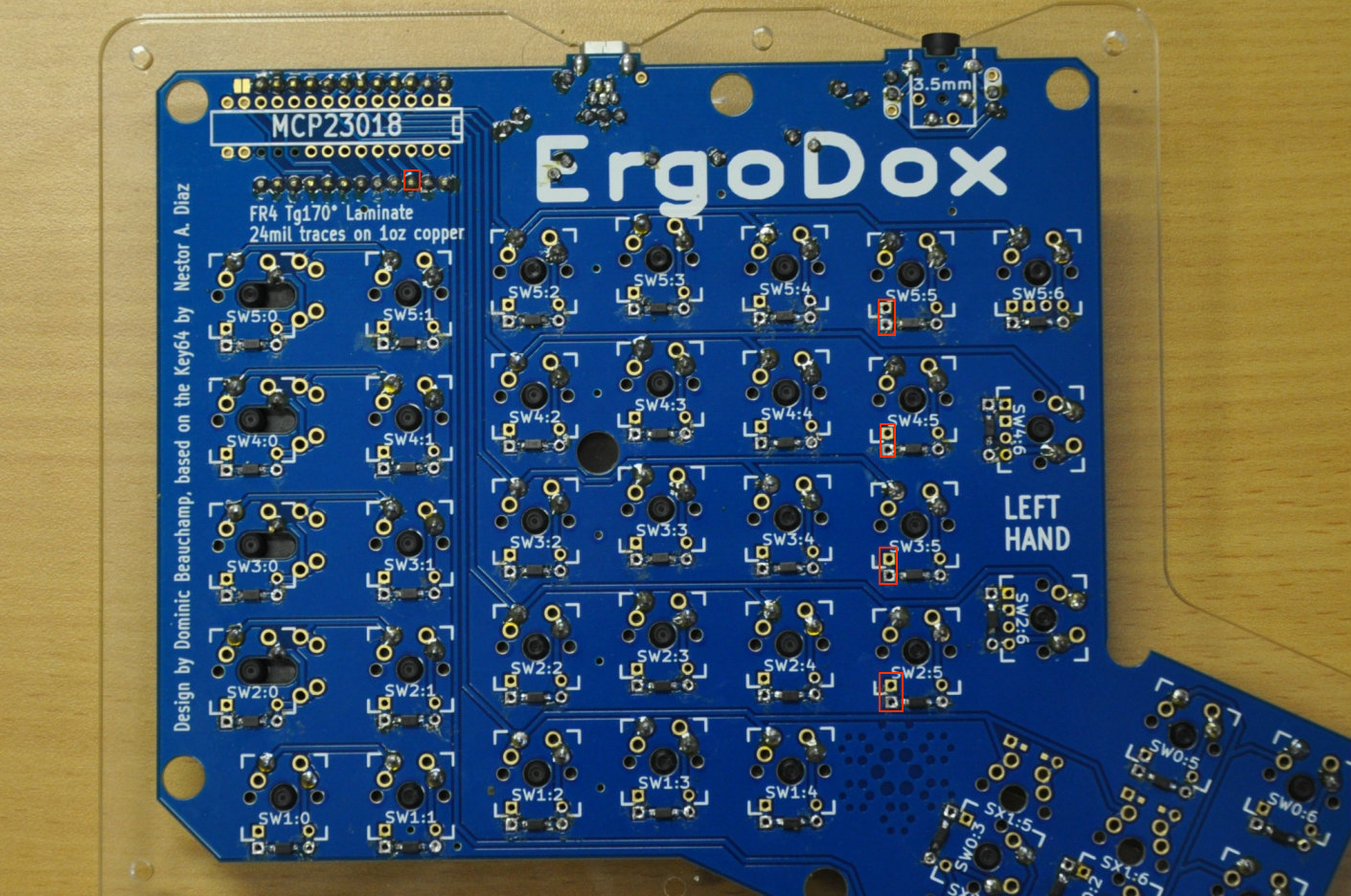
- ergodox_.jpg (371.32 KiB) Viewed 3436 times
Posted: 20 Nov 2013, 17:35
by Muirium
Odd. Might be a good idea to re-upload the software to the Teensy. Is the Ergodox controller under active development? Newest version if so.
Hardware wise, it's possible the Teensy itself is broken on that pin.
Posted: 20 Nov 2013, 17:42
by Half-Saint
I downloaded this guy's layout (.hex) and uploaded it to Teensy about an hour ago:
https://www.massdrop.com/ext/ergodox/?r ... ef6b32a7fb
Posted: 20 Nov 2013, 17:50
by Half-Saint
When I think about it... this test doesn't make any sense because it'll work even, if nothing is soldered to the board. It's basically just testing the traces on the PCB for continuity. Doesn't help find out why the switches aren't working.
I tested the diodes and they check out fine. Orientation is correct. Seriously, WTF?
Posted: 20 Nov 2013, 17:57
by Muirium
Half-Saint wrote:When I think about it... this test doesn't make any sense because it'll work even, if nothing is soldered to the board. It's basically just testing the traces on the PCB for continuity. Doesn't help find out why the switches aren't working.
That's pretty much exactly what it is: just a test of your solder joints on those traces. I think there might be something wrong with the Teensy on that pin, or at least how it connects to the PCB. You could try desoldering it for another go. (Or pulling another Teensy out of a drawer, just to rule it out…)
Posted: 20 Nov 2013, 18:01
by Half-Saint
Desolder the Teensy? I'd rather be shot...
Posted: 20 Nov 2013, 18:07
by Halvar
If a whole column of switches isn't working, I'd say it's not really probable that it has to do with failures of the switches themselves. Like Muirium said, what I think you want to check is the solder point that connects PCB and teensy (or even the controller on the teensy) for that column, and also that the PCB trace of that column is insulated against other signals.
Posted: 20 Nov 2013, 18:18
by Half-Saint
Halvar wrote:(or even the controller on the teensy) for that column, and also that the PCB trace of that column is insulated against other signals.
Holy crap, I found it! I tested for continuity between B1 and the controller and there was none! All I needed was a little bit more solder on the B1 pin om the top side.
Now it works! Thanks guys

Posted: 20 Nov 2013, 19:06
by Muirium
Great stuff. Now keep your multimeter handy, this kind of thing is his job!