Page 7 of 23
Posted: 21 Jul 2013, 19:58
by Muirium
Plaintext based diagrams! All right. Side views of what I was thinking. They are both like this along their entire width, with the back of keyboard to the left:
Stepped Body
Code: Select all
+==============================================================================+
|                                                                              |
|                       +======================================================+
|                       |
+=======================+
Where the base is stepped into two different sections, joined by more side layers and appropriate standoffs.
or
Added Box
Code: Select all
+==============================================================================+
|                                                                              |
+== ======= ======= ====+======================================================+
|                       |
+=======================+
Where a second box is added on the underside, with minimal changes to the previous design. Just some holes to allow internal cable routing.
I've been thinking about something like this for my own Bluetooth compatible design, where the back edge would have a hole in the metal for a plastic radio window. This is the most artful way I've come up with to make enough space for the battery and additional components for Bluetooth. Plus a USB hub if I can!
Posted: 22 Jul 2013, 07:00
by mtl
Here's how it looks from the side with a 3 mm basement layer:
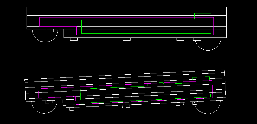
- basement.png (6.6 KiB) Viewed 5661 times
The purple box is about the absolute maximum internal space, if you hacked at the key switches and there were no wires/diodes to speak of. The green box is the maximum space required for the controller. I'm on the road now and don't have precise measuements for it. The parts overlapping in the picture are the grey ribbon sockets, which can be removed from the board.
I think it works out well, and gives some more breathing space for the Teensy and other internal components.

I had to get creative with the screw holes to get it to work.
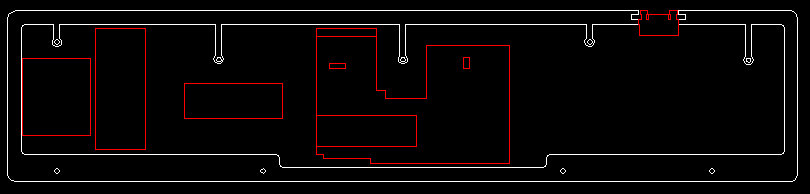
- basement-layer.png (2.92 KiB) Viewed 5661 times

- upper-part-bottom.png (2.45 KiB) Viewed 5661 times
- middle.png (2.62 KiB) Viewed 5661 times
Posted: 22 Jul 2013, 13:44
by Muirium
Looking good. The incline seems a bit shallow, though. I use my keyboards almost flat and that looks shallower an angle than even Apple's current keyboard:

If you've got a keyboard you're already comfortable with as a model, you could try some measurements. Or of course you're already well ahead of me and this is what you're going for!
Posted: 23 Jul 2013, 03:41
by mtl
Yeah it's at a 3 degree angle in that picture. My keyboard tray does up to -10 or -15 degree negative angles and was hoping to keep this keyboard flat to use it like that. But the tray is still new and I don't know yet what angle I prefer. Also SA keycaps tend to have a more dramatic rise in higher rows which adds to the effective angle.
Posted: 23 Jul 2013, 09:01
by matt3o
my only concern is about those little insets for the screw holes in the upper part. I have no idea how they are going to work. Anyway I'm probably going to have my layout cut this week so I'm gonna guinea pig it for you

Posted: 23 Jul 2013, 11:04
by Muirium
Thanks Matt! Those do look quite the critical point of failure if done wrong. The sections where there's blank space (like under the spacebar, or around it on HHFox) are fine, but squeezing in between the mass of keys in the top rows is quite the challenge.
All the more glory if you pull it off!
Posted: 24 Jul 2013, 06:54
by mtl
Sounds good.. I hope it works out well for you, matt3o!
Posted: 24 Jul 2013, 17:07
by kps
matt3o wrote:Just got the reply from the laser cutter. Unfortunately they can't make it by the end of July and we have to wait until September.
Excellent. I should be in for a battleship-sized plate by then. I'm just waiting for the second half of my Round 4 caps to arrive so I can finalize my layout with assurance that I actually have the parts.
Posted: 26 Jul 2013, 12:05
by matt3o
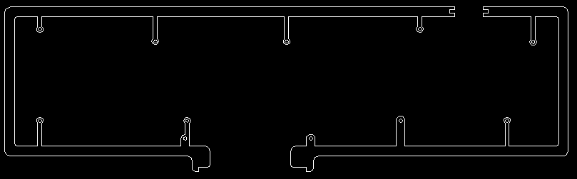
Broadmonkey's updated board
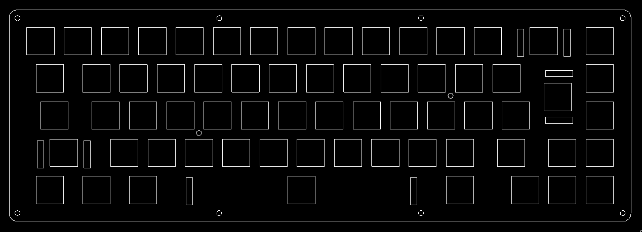
- broadmonkey.png (4.27 KiB) Viewed 5569 times
please double-check!
Posted: 26 Jul 2013, 17:02
by kps
A couple quick (?) questions.
- Any tips on using DraftSight for this purpose? Specifically moving/copying groups of key holes on the appropriate ⅛u grid.
- Is the cost primarily metal plus laser time (roughly, cut length), or are there other factors to be aware of?
Posted: 26 Jul 2013, 17:24
by matt3o
kps wrote:Any tips on using DraftSight for this purpose? Specifically moving/copying groups of key holes on the appropriate ⅛u grid.
Use array command to build your initial 15x5 (or whatever grid), then start to move holes around.
I use the following formula to space slots. Please note that I use 19mm spacing instead of 19.05mm as suggested.
Replace k1u with the units of the first key and k2u with the units of the second.
Eg:
19.25mm is the distance between a 1.5u and a 2u key (side to side, not centers). I don't know if this is the best (or even correct) way but it worked for me so far.
kps wrote:Is the cost primarily metal plus laser time (roughly, cut length), or are there other factors to be aware of?
yes the cost is metal + cut length. I'm not aware of any additional cost, apart from shipping. As a rule of thumb don't create holes smaller than the sheet thickness.
Posted: 02 Aug 2013, 04:24
by mtl
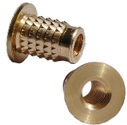
Here are some new parts I am considering:
Threaded inserts (
and these), to keep the bottom keyboard surface mostly flat, instead of having screws and nuts coming out:
Micro USB breakout board for the detachable USB cable port:
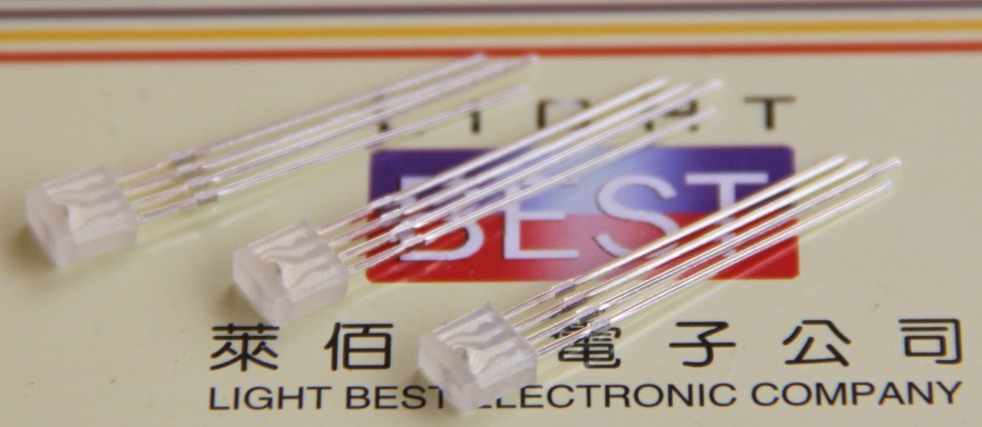
Rectangular RGB LEDs for key lock indicators:
These LEDs are about 2.5mm x 5mm x 5mm, and (incidentally) would probably fit well inside (modified or
custom) MX switches for a fully backlit keyboard, if that's your thing.
Posted: 02 Aug 2013, 19:44
by Muirium
Custom switches? (Follows link.) Oh, right, custom top shells:

Trouble is the bottom of Cherry MX switches is designed for a two pin LED, as well. There's only two holes down there, neatly set aside for a regular LED's legs. I'd like to see RGB LEDs across a keyboard, but I can't see it being achieved with these components.
Posted: 02 Aug 2013, 20:26
by photekq
Muirium wrote:Custom switches? (Follows link.) Oh, right, custom top shells:
Trouble is the bottom of Cherry MX switches is designed for a two pin LED, as well. There's only two holes down there, neatly set aside for a regular LED's legs. I'd like to see RGB LEDs across a keyboard, but I can't see it being achieved with these components.
There are actually four holes there. Two for LEDs, two for diodes.
Posted: 02 Aug 2013, 20:45
by Muirium
That's true, but using the diode ones too would spread the LED's legs wide apart indeed. I don't know if it's doable while seating it right.
Posted: 12 Aug 2013, 18:46
by mtl
matt3o wrote:I asked about anodized alu. It's very cheap if we anodize before cutting, if we anodize after the cut it costs x5.
speaking of $$$ it would be +€5/kg or +€15-20/kg
Any further thoughts on anodization? It would be great to get at least the top layer anodized black, though I imagine we would have to form some consensus on the color(s) to be used, if any.
Posted: 12 Aug 2013, 20:03
by matt3o
I'm all in for anodization, all in the same color of course (I'd say silver or black). I would anodize all the layers, the cost should bet around 30eur divided by the number of orders.
BTW the keyboards will be pretty expensive so I need to know what you guys think about it
Posted: 12 Aug 2013, 20:36
by Muirium
I'm still in. No anodisation for me though. Well, unless it's just the middle layers.
Posted: 13 Aug 2013, 00:43
by Zifle
I'm still in, although I'll have some changes to my design (with more layers, too). I'd join in on the anodization, but I might get a steel plate instead, haven't exactly decided yet....
Posted: 13 Aug 2013, 05:05
by mtl
matt3o wrote:BTW the keyboards will be pretty expensive so I need to know what you guys think about it
It's hard to say until the quote comes back. My design has 6 layers (1x alu 1.5 mm, 2x steel 3 mm, 3x steel 1.5 mm). Can you give a ballpark on what you think this may cost? I suppose it may be difficult to divide the costs among the people on this mini-GB. Do you have any thoughts on how to go about that?
Posted: 13 Aug 2013, 09:00
by matt3o
mtl wrote:It's hard to say until the quote comes back. My design has 6 layers (1x alu 1.5 mm, 2x steel 3 mm, 3x steel 1.5 mm). Can you give a ballpark on what you think this may cost?
I should see the design. Are all the 1.5 layers plates?
mtl wrote:I suppose it may be difficult to divide the costs among the people on this mini-GB. Do you have any thoughts on how to go about that?
Yes, that won't be easy. It will depend on the number of switch holes you have.
So a side should be relatively inexpensive (I guess 15-20 euros) while the plate should go in the 60-70 range. Steel is cheaper.
Since once I have the quote I have to pay really fast, if you participated
please send me a PM with your email (an email you can read in work-hours).
Also, consider that you might spend 120-150 per case (we hope to reduce that slightly but take that as a reference). If you are not ready to hand that, don't participate just for the sake of getting a quote! If you do not confirm your purchase we have to remove your design and request a new quote.
Posted: 13 Aug 2013, 11:15
by Zifle
When are our designs due to be done / when will you request a quote?
Posted: 13 Aug 2013, 11:47
by Muirium
Could you post the current revision of your HHFox design, Matt? Specifically: 3D file(s) containing all the layers, with metric dimensions. I'm going to try some 3D modelling of my own, and it really helps to have a template to start from. With a real design file in your chosen format, I can also quickly rule out which software can't open it! Thanks.
Posted: 13 Aug 2013, 12:00
by matt3o
Zifle wrote:When are our designs due to be done / when will you request a quote?
no fixed date, I'd say first week of Sept.
Muirium wrote:Could you post the current revision of your HHFox design, Matt? Specifically: 3D file(s) containing all the layers, with metric dimensions.
Sure thing! I'm in the middle of my main PC linux reinstall. I'll post as soon as I'm done.
Posted: 13 Aug 2013, 12:04
by Muirium
Cheers. Fortunately this is all unions and intersects of rectangles, with cylinders for the screws, so there's a chance I can pull it off. The tough part will be finding an app that doesn't drive me crazy. Blender any good for this?
Posted: 13 Aug 2013, 12:16
by matt3o
Muirium wrote:Cheers. Fortunately this is all unions and intersects of rectangles, with cylinders for the screws, so there's a chance I can pull it off. The tough part will be finding an app that doesn't drive me crazy. Blender any good for this?
I can't put my head around blender but it is said to be good.
it should import DXF with no problem, also the layers are just extrusions so it should be really easy to master a 3D version.
Posted: 13 Aug 2013, 16:40
by Acanthophis
matt3o, what do you reckon how much a TKL case for the Phantom will be? Below 200 EUR?
Posted: 13 Aug 2013, 16:59
by matt3o
Acanthophis wrote:matt3o, what do you reckon how much a TKL case for the Phantom will be? Below 200 EUR?
not sure I understand. you already have the plate I guess, do you need just the sides and bottom?
Posted: 13 Aug 2013, 18:06
by Acanthophis
I have a plate but I don't think I can incorperate it into sides and bottom.
So I planned with plate, sides, and bottom.
Posted: 13 Aug 2013, 19:26
by matt3o
Acanthophis wrote:I have a plate but I don't think I can incorperate it into sides and bottom.
So I planned with plate, sides, and bottom.
I think it should go in the 150-160 euro range