Page 19 of 23
Posted: 04 Oct 2013, 12:06
by matt3o
Muirium wrote:By the way, you guys aren't soldering up your matrices with the keyboard's weight resting on the switches, are you? Matt warned me against that, especially with clicky MX like my greens. The heat can mess up their mechanism pretty quick, when the slider is close.
when you flip your plate the weight is distributed among all the switches, so they don't get pressed (especially greens). The bottom line is: do not solder (or desolder) when the key is pressed. This is true for clicky and tactile switches and you are not very good or fast at soldering (like any average skilled human being

).
Posted: 04 Oct 2013, 12:14
by Muirium
Ah! Important distinction. Even my heavy little board doesn't click every switch at once when turned upside down, though some definitely give way. I'll likely prop it up from the sides when I solder.
Do you suggest soldering the matrix on the bare plate or with one (or more) of the underlying layers attached? I want to steer clear of the obstacles formed by the hidden screw mounts, but I need enough space to work, too.
Posted: 04 Oct 2013, 12:59
by matt3o
solder on the bare plate and use the sides as a stand-off (hope it is clear what I mean)
Posted: 04 Oct 2013, 13:01
by Zifle
I didn't have any trouble with it, with some light blues. None of them got actuated, due to the weight distribution, as Matt3o mentioned. So I wouldn't worry about it. I did have some solders where I went above and beyond the time it usually takes for a joint.
Posted: 06 Oct 2013, 21:15
by Muirium
As for electric insulation / Teensy mounting, you mentioned adhesive vinyl film. Is this the kind of stuff?
http://www.ebay.co.uk/itm/A4-Sheet-1m-R ... 2c64711a0a
And how much of it should I get? I've a few experiments in mind besides this keyboard, actually.
Posted: 06 Oct 2013, 21:32
by matt3o
Muirium wrote:As for electric insulation / Teensy mounting, you mentioned adhesive vinyl film. Is this the kind of stuff?
http://www.ebay.co.uk/itm/A4-Sheet-1m-R ... 2c64711a0a
And how much of it should I get? I've a few experiments in mind besides this keyboard, actually.
yes, it is that. An A4 sheet is more than enough. I can send you some with next shipping if you want.
Posted: 07 Oct 2013, 14:26
by Muirium
I'm thinking of enough for this keyboard and a few other Teensy based projects. The next thing I have lined up from you is (both ANSI and ISO parts of) DSA Dolch, hurrah! Might take a while yet.
By the way, you ordered some windowed caps with your DSA Dolch, didn't you? If you have any spares, count me in! I forgot to consider lock indicators. A function layer lock light would be sweet.
Posted: 07 Oct 2013, 14:36
by matt3o
Muirium wrote:I'm thinking of enough for this keyboard and a few other Teensy based projects. The next thing I have lined up from you is (both ANSI and ISO parts of) DSA Dolch, hurrah! Might take a while yet.
that reminds me that I have to contact jackass to ask why this is taking so long.
Muirium wrote:By the way, you ordered some windowed caps with your DSA Dolch, didn't you? If you have any spares, count me in! I forgot to consider lock indicators. A function layer lock light would be sweet.
Yes I should have 4 (or was it 8)... either case I can part 1 or 2.
Posted: 07 Oct 2013, 14:44
by Muirium
Awesome!
I must look at Hasu's code and see if I can figure out how to actually make a layer light, of course…
Posted: 10 Oct 2013, 12:33
by Zifle
Has nobody made further progress on their boards? We need updates here!
I finally got time, and proper weather, to take some outdoor pictures of my board, so I've updated my album;
http://imgur.com/a/8J3Ej#YM19QOj
Posted: 10 Oct 2013, 12:43
by matt3o
thanks Zifle for the update! Your board looks gorgeous! I love the keycap set (and your cat of course).
I'll be leaving for US tomorrow and I'll stay there for 1 month, so unfortunately I will be able to work on the HHFox only starting from mid November.
I hope to see others' creations in the meantime!
Posted: 10 Oct 2013, 13:00
by Muirium
The master keeps his own work for last!
A month might just be long enough for me to get mine together. I have the soldering iron on right now, having prised the empty case apart from a week's worth of bolt training. Let's see now…
Posted: 10 Oct 2013, 13:49
by mtl
Hahahah.. The cat picture is great.

Were you able to get shorter screws for the bottom? Would love to see how the threading approach turned out.
My board has been at a standstill all week with under half of the columns wired. There is a deadline at work and not much time for anything else.

Posted: 10 Oct 2013, 13:56
by Muirium
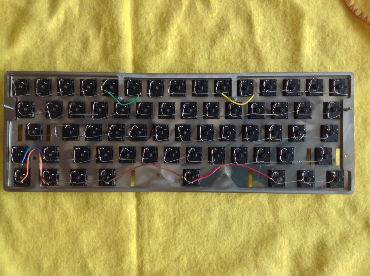
Okay, half an hour with the soldering iron, bending diodes along the way, and I have the first row done. I've done things differently from
Matt3o's guide because my design prevents that:
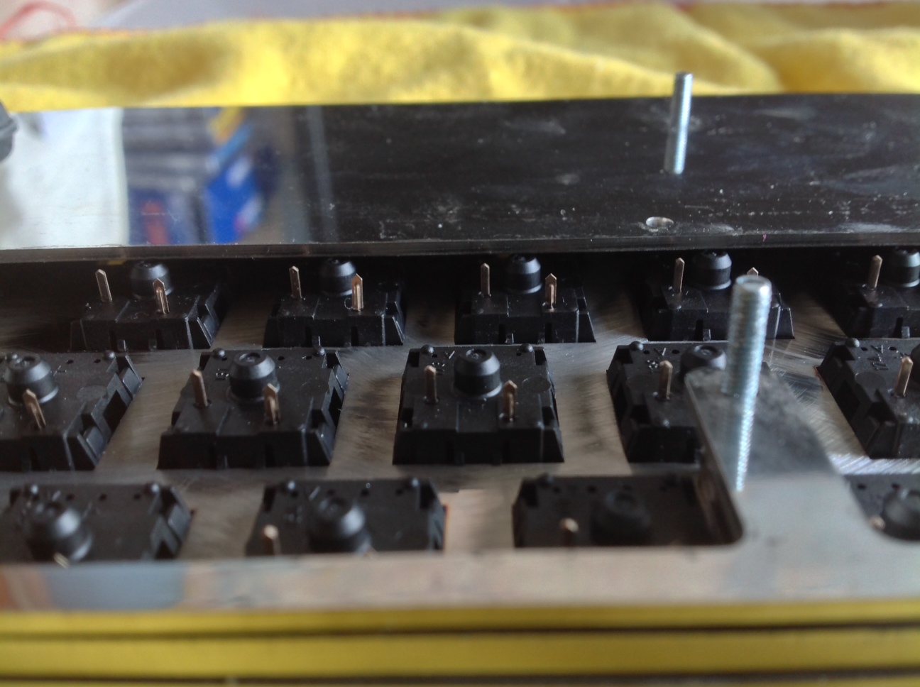
- photo 1.JPG (289.84 KiB) Viewed 5517 times
Note the slender clearance with the shiny layer at the back — the half-height mezzanine layer — which likely means some pin bending or trimming for that half of the keyboard. I'm attaching my diodes nice and flush with the switch housings to give me leeway on that. I'm about as quick with the iron as Matt, so no plastic was harmed in the process.
But the bigger issue is the screw insets, which keep my case nice and tight, with screws mounted between the switches instead of around the outside. I actually did my soldering with one extra layer still in place, as a guide:
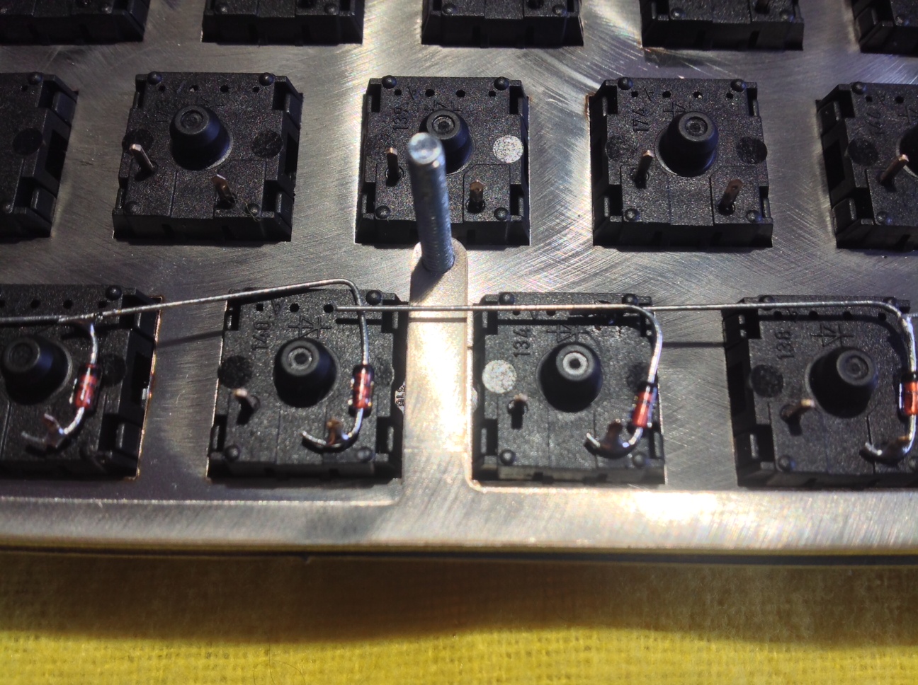
- photo 4.JPG (482.14 KiB) Viewed 5517 times
Obviously I'll have to route the matrix around those insets, with insulated wires like the columns use.
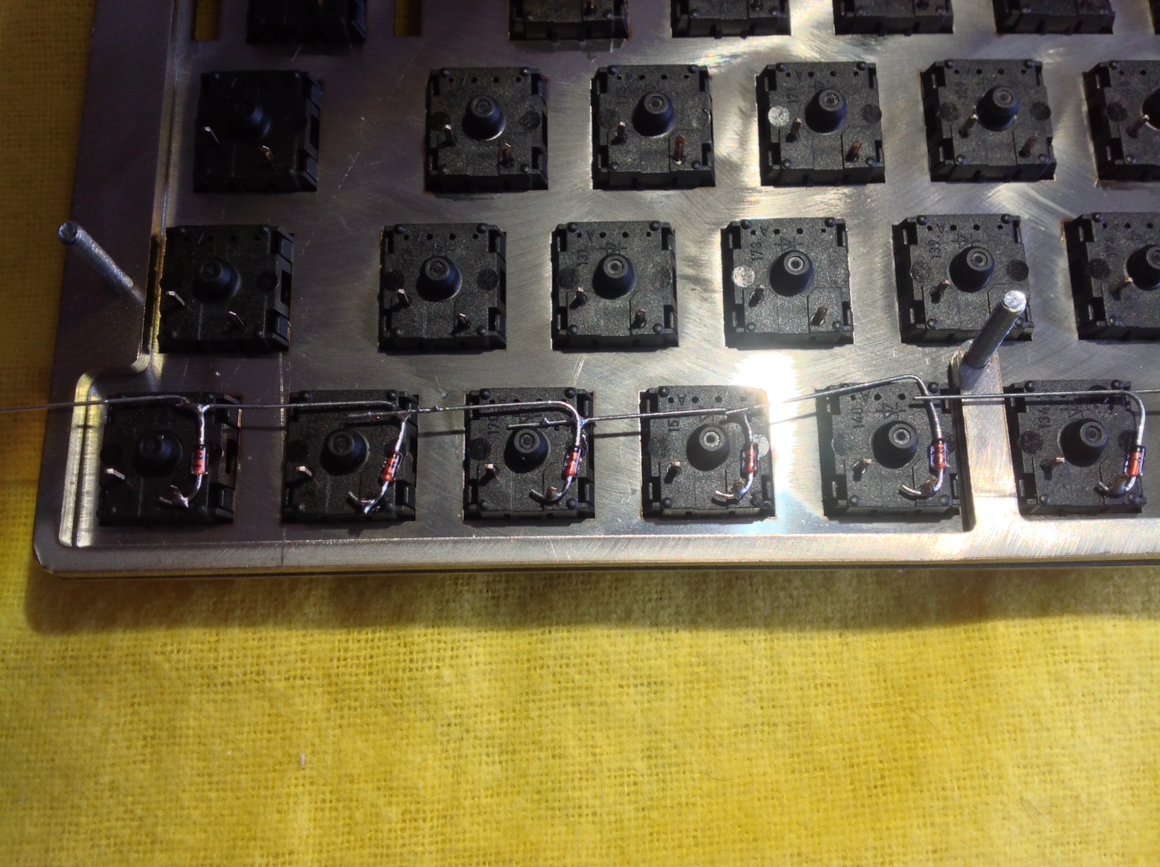
- photo 3-1.JPG (486.59 KiB) Viewed 5517 times
Working on this is quite amusing with all the internal shiny!
- photo 5.JPG (473.88 KiB) Viewed 5517 times
Those joints are all done and continuity test fine. It's definitely a hand made look building up inside this keyboard!
Shall I work on the other rows today or is there an obvious gotcha that I'm overlooking?
Posted: 10 Oct 2013, 14:01
by matt3o
you know that you have to go around the screw inserts, right? not above! (sorry if it sounds silly
)
of course start from the most complex part and leave the easy tasks at the end.
Posted: 10 Oct 2013, 14:06
by Muirium
Yes! That's what I mean about using insulated wires (like with the columns) for jumping around those sections. The diodes which cross them currently due to be chopped. But they solder nicer with legs in place to help them sit right.
Posted: 10 Oct 2013, 14:46
by matt3o
Muirium wrote:Yes! That's what I mean about using insulated wires (like with the columns) for jumping around those sections. The diodes which cross them currently due to be chopped. But they solder nicer with legs in place to help them sit right.
you are doing well, then. I wouldn't solder the diodes so close to the switch chassis even though you have to cut the pins a little, but it's just a personal preference.
For the HHFox I might try an home made PCB... will see.
Posted: 10 Oct 2013, 14:51
by Muirium
<Puts down soldering iron.> PCB!? That's just crazy talk! <Gets back to the whiff of fresh solder.>
So far, this is going pretty easily. I expect that, as usual, I'll find the easy parts harder than the hard ones…
Posted: 10 Oct 2013, 15:07
by Muirium
By the way: how far do the stabs stick down through their mounting holes on the plate? Anything we newbs should look out for?
Posted: 10 Oct 2013, 15:58
by matt3o
Muirium wrote:By the way: how far do the stabs stick down through their mounting holes on the plate? Anything we newbs should look out for?
never had an issue with those. they stick just 1 or 2 mm. nothing to worry about
Re PCB: I said home made PCB!
which is as fun as hand wiring
Posted: 10 Oct 2013, 16:42
by Muirium
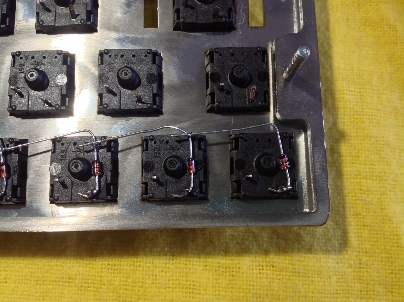
Rows all done.
- photo 1-2.JPG (476.26 KiB) Viewed 5499 times
Trimming the jump wires was the fiddliest part. Miniature soldering is fine, but trimming the ends of wires without cutting right through them never seems to get any easier! You use a scalpel to expose the middle bits of wire for your columns, don't you? Hmm. Not looking forward to working my way around that!
Posted: 10 Oct 2013, 16:52
by matt3o
seems good. a bit messy but should work
I would cut the excesses where possible.
when you have to peel the wire at the edges the easiest is with your teeth
If you can't peel them in the middle make small chunks and solder them one by one. longer but safer.
Posted: 10 Oct 2013, 16:59
by Muirium
Indeed, I've only done the "rough trimming" pass on the legs so far, not the "obsessive compulsive trimming" pass! Fortunately the conductivity meter says all five rows are perfect.
Posted: 10 Oct 2013, 19:20
by Muirium
Last picture for the day (as it's getting dark already) now that the columns are done:
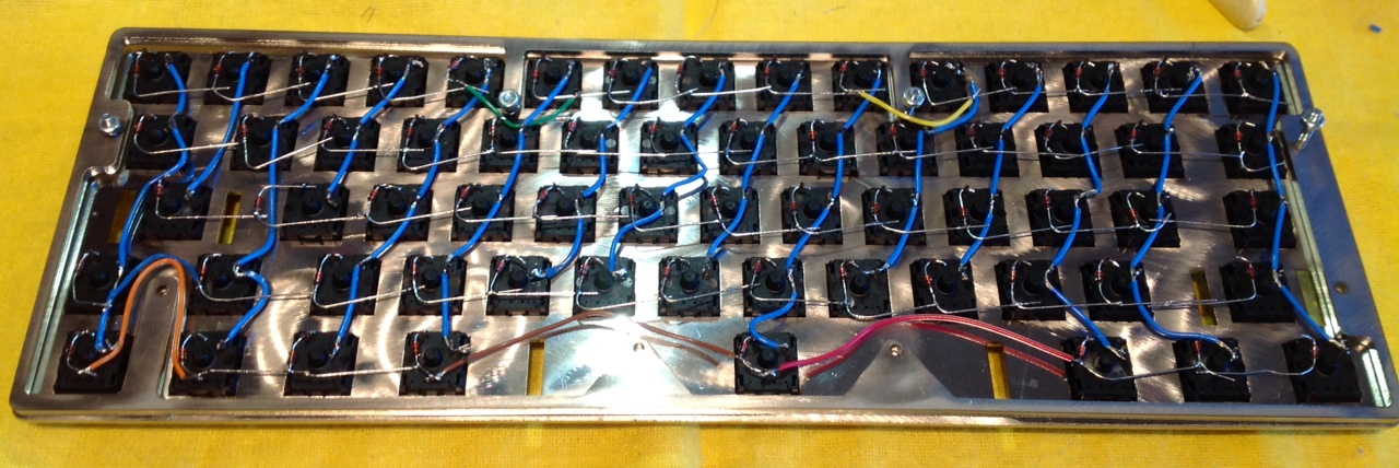
- photo-2.JPG (287.01 KiB) Viewed 5484 times
Next session: Teensy! Speaking of which, Matt, could you share your Brownfox code?
Posted: 10 Oct 2013, 19:44
by matt3o
great progression Muirium.
Firmware
Posted: 10 Oct 2013, 19:54
by Muirium
Cheers. I'll see if I can figure out what you're up to, and, if it builds and works, I'll go into detail here. My layout should be the simplest thing about my keyboard, compared to the risky and fortunately successful case, but if anyone can stumble on the final straight it's me!
Posted: 10 Oct 2013, 20:15
by matt3o
post your matrix and your teensy pinout and I'll help you with the firmware if needed.
Posted: 11 Oct 2013, 01:25
by mtl
Whoa.. that's some quick wiring! I am a slow poke.
Posted: 11 Oct 2013, 01:32
by Muirium
Took about five hours, and as many cups of tea. I believe Matt3o is quicker and surely more precise. But I'm pleased with it for a first timer. Best of luck with yours! Be neat.
Posted: 11 Oct 2013, 12:00
by damorgue
Muirium wrote:
And the other is a rather handsome one of these:
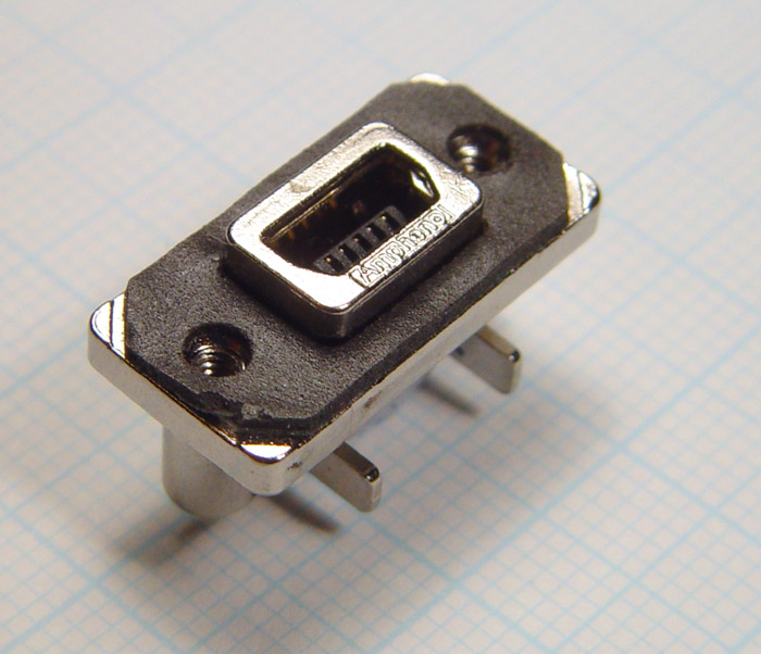
Did matteo send that one as well or did you find that one?
Where is it from, and where can I get one?