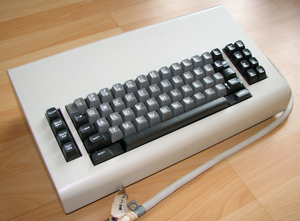
My goal for this project is to get a DisplayWriter keyboard (beam spring) and the kishsaver (a Model F) converted to USB and usable. They don't have protocols that are usefully convertible, because they don't send release codes (or rather, they only send them for one or two keys).
Fully replacing the controller is an option - dfj has done so with a 122-key F, and it works well. But I fancied taking a different route, preferring to drive the IBM capacitive sensing chip by replacing the CPU. This means desoldering the original CPU, which naturally carries some risk of damage, but I've been lucky so far!
Some of the information here could of course be useful for replacing the 8048 in other, non-IBM, keyboards. The 8048 pins that might be used to scan a switch matrix are marked in green on this pinout:
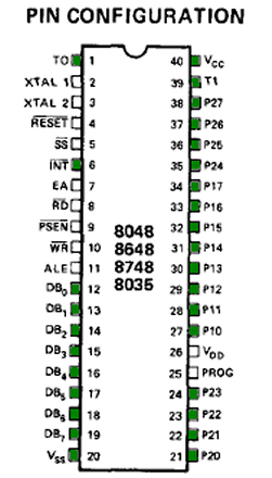
- 8048_replace.png (56.45 KiB) Viewed 9500 times
They are never all used just for reading the matrix. Some will be driving the external interface, and some may be driving LEDs. So a Teensy should have enough pins for any case, just! OTOH, something like a Teensy++ would make it easier to make a logical mapping between the 8048's three 8-bit ports, since the Teensy++ has four full ports (and/or might make physically mounting it in place easier, but more of that later).
Of the IBM controllers, there's a distinct similarity in pin use between the PC/XT and DisplayWriter (although of course there are big differences in pin use for the external interface):
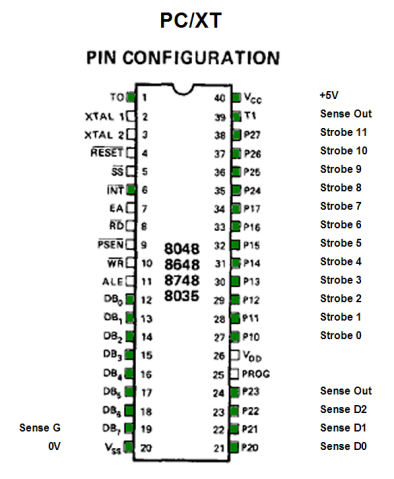
- 8048_replace_PCXT.png (82.71 KiB) Viewed 9500 times
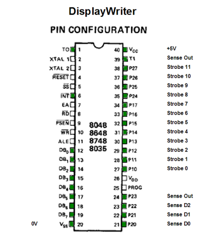
- 8048_replace_DisplayWriter.png (84.2 KiB) Viewed 9500 times
The AT uses a multiplexer for driving the strobe lines, so it doesn't use many pins at all. This same arrangement is also used in at least some of the 122-key terminal controllers:
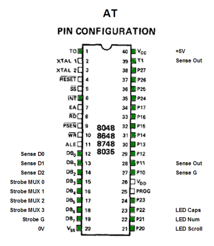
- 8048_replace_AT.png (78.69 KiB) Viewed 9500 times
And finally the kishsaver simply doesn't have many keys, so has fewer strobe lines:
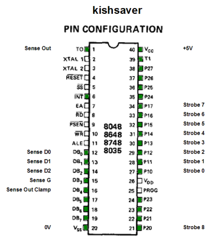
- 8048_replace_kishsaver2.png (81.44 KiB) Viewed 9323 times
edit: updated kishsaver pinout, having discovered that there is a buffer between Sense Out Clamp and Sense Out (unlike the other boards).