The theory behind this is fairly simple, mostly because its a one sided PCB.
You look see which parts of the PCB where the Numpad is that you need to keep. In the case of the Dell, we want to keep the connector, and the LEDs. Being a Mac user I don't need the scroll lock LED, as we are removing the numpad, we also don't need the Numlock LED, you can either bend and break these off, or desolder them off.
Once you know which bits you need you basically follow the tracks in both directions from where you plan to cut off the Numpad portion of the PCB, then solder a wire between the first two contact points you find. Much easier than trying to solder onto a track.
We also need to make sure that any of the traces that connect up to keys on the side of the keyboard we want to keep are connected up again. Using the same method of following traces both directions from the cut. If one end of the trace ends on a key we are chopping off, there is no need to reconnect it.
Watch out for the jumpers that come through on the front of the board.
Here is the guide I made to resolder from.
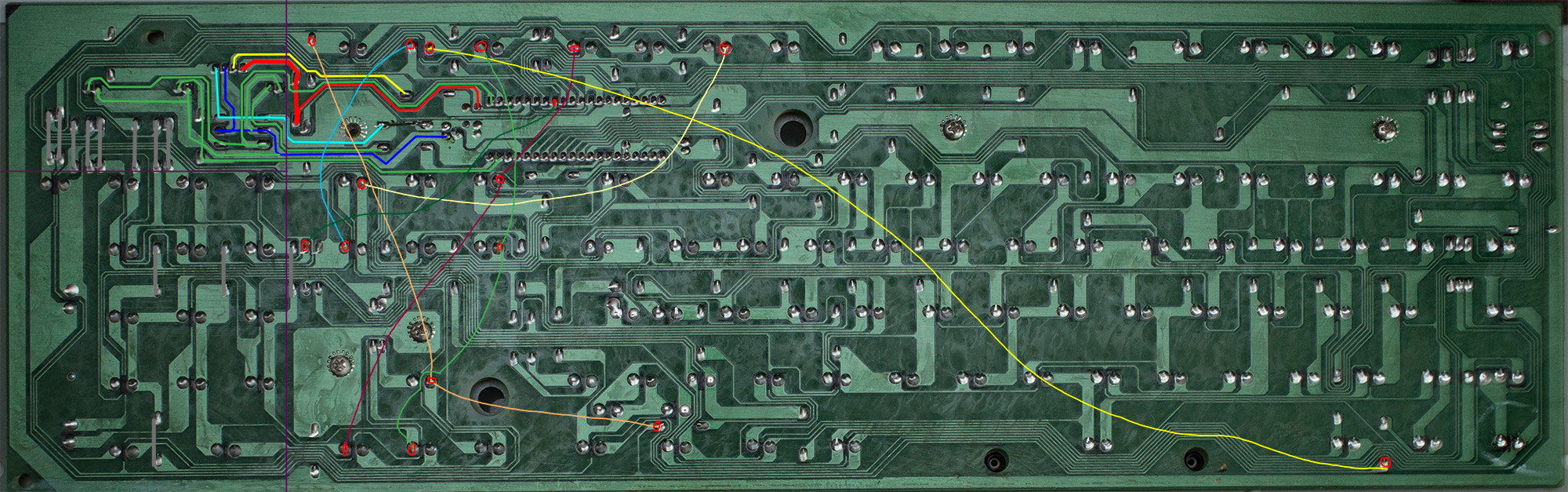
- DellConversion.jpg (514.43 KiB) Viewed 3160 times
The cluster of lines on traces show the points you need to connect via wires for the connector LED's and resistors. The purple lines show where I cut off my PCB, you can however trim off a bit more.
The more 'wavy' lines are where we reconnect up the tracks that go off the main part of the PCB but come back on else where.
If you find a key isn't working, basically look to see where its soldered onto the board, follow the tracks and see if it goes off the main part of the PCB onto the numpad.
With my mod, I cut the traces along the vertical purple line first but without breaking off the PCB, this meant I could easily work and resolder, while also being able to plug in the keyboard to check which keys were/were not working.
I am not responsible if you break your keyboard, however I am happy to help.


